GE IS200AEPCH1ABC IS200BPPBH2BJD Spare Mark VI Automation: Exciter Control Replacement for Turbine Downtime Recovery
The GE IS200AEPCH1ABC and IS200BPPBH2BJD are original exciter control modules engineered for GE Mark VI turbine control systems — one of the most widely deployed distributed control architectures in power generation, oil & gas, and heavy industrial facilities worldwide. When either board fails, the consequences extend beyond a single component: turbine excitation loss triggers emergency shutdowns, production halts, and costly unplanned outages. Maintaining a verified, tested spare of both the IS200AEPCH1ABC and IS200BPPBH2BJD in your critical spare inventory is the most direct strategy to compress mean time to repair (MTTR) and restore generation capacity within hours rather than days.
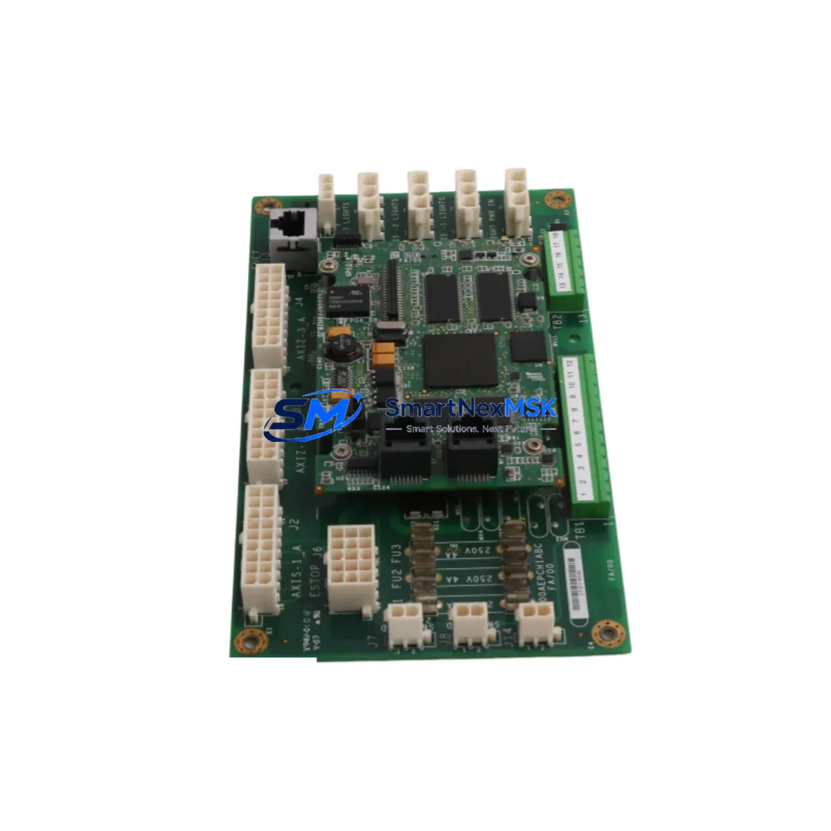
These modules operate within the Mark VI exciter control cabinet, managing field voltage regulation, AVR feedback loops, and excitation protection sequences. The IS200AEPCH1ABC functions as the exciter protection and control board, while the IS200BPPBH2BJD serves as the power supply and backplane interface board — both must be operationally matched and firmware-compatible for stable exciter performance. Sourcing both as a paired spare set eliminates diagnostic ambiguity during fault isolation and accelerates board-swap procedures on site.
Every unit shipped from our inventory undergoes pre-shipment functional verification, visual inspection for component integrity, and packaging in anti-static ESD-safe materials. A 12-month warranty covers manufacturing defects and operational failure under normal industrial service conditions. We support long-term supply continuity for legacy Mark VI installations where OEM availability has been discontinued or lead times exceed operational tolerance.
Spare Maintenance Table
| Parameter | IS200AEPCH1ABC | IS200BPPBH2BJD |
|---|---|---|
| Brand | GE (General Electric) | GE (General Electric) |
| Series | Mark VI Exciter Control | Mark VI Exciter Control |
| Module Function | Exciter Protection & Control Board | Power Supply & Backplane Interface Board |
| System Compatibility | GE Mark VI Turbine Control System | GE Mark VI Turbine Control System |
| Application | Power Generation, Oil & Gas, Heavy Industry | Power Generation, Oil & Gas, Heavy Industry |
| Origin | USA | USA |
| Condition | Original Spare / Tested | Original Spare / Tested |
| Installation | Mark VI Exciter Cabinet Backplane | Mark VI Exciter Cabinet Backplane |
| Operating Environment | Industrial Control Cabinet, 0–55°C | Industrial Control Cabinet, 0–55°C |
| Maintenance Recommendation | Replace on fault code or AVR instability | Replace on power fault or backplane error |
| Warranty | 12 Months | 12 Months |
| Pre-Shipment Test | Functional Verification Included | Functional Verification Included |
Maintenance Planning for Continuous Operation
A structured maintenance plan for Mark VI exciter systems extends well beyond the IS200AEPCH1ABC and IS200BPPBH2BJD boards themselves. During scheduled outages or corrective maintenance events, maintenance engineers should treat the exciter cabinet as a system — not a collection of isolated components. When replacing either board, the following associated components warrant simultaneous inspection or proactive replacement:
The IS200EPCTG1A exciter protection card works in close coordination with the IS200AEPCH1ABC; degraded protection logic on either board can produce nuisance trips or masked faults. The IS200VTURH1BDD turbine control I/O board interfaces with exciter feedback signals — connector wear and signal drift on this board can mimic exciter board failures during fault isolation. The IS200DSPXH1D digital signal processor board handles AVR computation and should be inspected for firmware version alignment whenever the AEPCH1 board is replaced.
On the power distribution side, the IS200BPPBH2BJD power supply board (the paired module in this listing) should always be replaced or bench-tested alongside the AEPCH1 board, as shared power rail degradation is a common root cause of dual-board failures. Inspect the Mark VI exciter cabinet terminal blocks and wiring harnesses for insulation breakdown, loose crimps, and corrosion — particularly on field voltage sense leads and AVR feedback wiring. The IS200STCIH1A static exciter control interface module and associated field flashing resistor assemblies should be checked for thermal stress and contact resistance.
For communication integrity, verify the Mark VI IONET or ARCNET communication module connections between the exciter controller and the main turbine control rack. Signal isolation barriers on analog exciter feedback channels should be tested for drift. If the installation includes a GE EX2100 or EX2100e exciter panel, confirm that the replacement boards are firmware-matched to the exciter panel software version to avoid initialization errors on restart.
Fuse holders and miniature circuit breakers within the exciter cabinet should be inspected and replaced on a time-based schedule regardless of apparent condition — these low-cost components are a frequent source of intermittent faults that are difficult to diagnose under load. Maintaining a cabinet-level spare kit that includes the IS200AEPCH1ABC, IS200BPPBH2BJD, and the above supporting components ensures that a single site visit can resolve the majority of exciter-related forced outage scenarios.
Site Replacement Workflow
Step 1 — Fault Isolation: Retrieve Mark VI diagnostic fault codes from the HMI or ToolboxST workstation. Distinguish between exciter board faults (AEPCH1 domain) and power supply/backplane faults (BPPBH2 domain) before pulling any hardware.
Step 2 — Safe Isolation: Follow site LOTO procedures. De-energize the exciter cabinet, discharge field voltage, and verify zero-energy state on all exciter bus bars before opening the cabinet.
Step 3 — Board Removal: Document connector positions and cable routing with photographs. Remove the faulty board using ESD-safe handling. Inspect the backplane connector for bent pins or carbon tracking before installing the replacement.
Step 4 — Replacement Installation: Install the IS200AEPCH1ABC or IS200BPPBH2BJD spare. Verify firmware version compatibility with the site’s Mark VI software revision. Re-seat all connectors and confirm backplane seating.
Step 5 — Commissioning Check: Re-energize in sequence per GE Mark VI commissioning procedure. Monitor AVR response, field current ramp, and exciter protection relay status on the HMI. Confirm no residual fault codes before returning the unit to service.
Step 6 — Documentation: Log the replacement in the site CMMS with board serial numbers, firmware versions, and fault history. Update the spare parts inventory record to trigger reorder of the consumed spare.
Spare Parts Support FAQ
Q1: Are the IS200AEPCH1ABC and IS200BPPBH2BJD compatible with all Mark VI exciter configurations?
These boards are designed for GE Mark VI exciter control cabinets. Compatibility depends on the specific Mark VI software revision and exciter panel configuration at your site. We recommend providing your site’s Mark VI software version and exciter panel model (e.g., EX2100, LCI) when ordering so we can confirm firmware alignment before shipment.
Q2: What pre-shipment testing is performed on these spare boards?
Each board undergoes visual inspection for component damage, ESD handling verification, and functional bench testing where applicable. Boards are shipped in anti-static packaging with a test report. The 12-month warranty covers operational failure under normal industrial service conditions from the date of shipment.
Q3: Can these boards replace older Mark VI exciter board revisions?
In many cases, later hardware revisions of the IS200AEPCH1ABC and IS200BPPBH2BJD are backward-compatible with earlier Mark VI exciter installations. However, firmware and hardware revision matching should be confirmed against your site documentation. Our technical team can assist with cross-reference verification prior to order confirmation.
Q4: What is your lead time and long-term supply availability for these boards?
We maintain stock of Mark VI exciter spare boards to support urgent replacement requirements. Standard lead time for in-stock units is 3–7 business days for international shipment. For sites with recurring maintenance needs, we offer reserved inventory arrangements to guarantee supply continuity for legacy Mark VI systems beyond OEM support windows.
© 2026 SMARTNEXMSK. All rights reserved.
Original Source: https://smartnexmsk.com
Contact: sales@smartnexmsk.com | +86 18259474341


