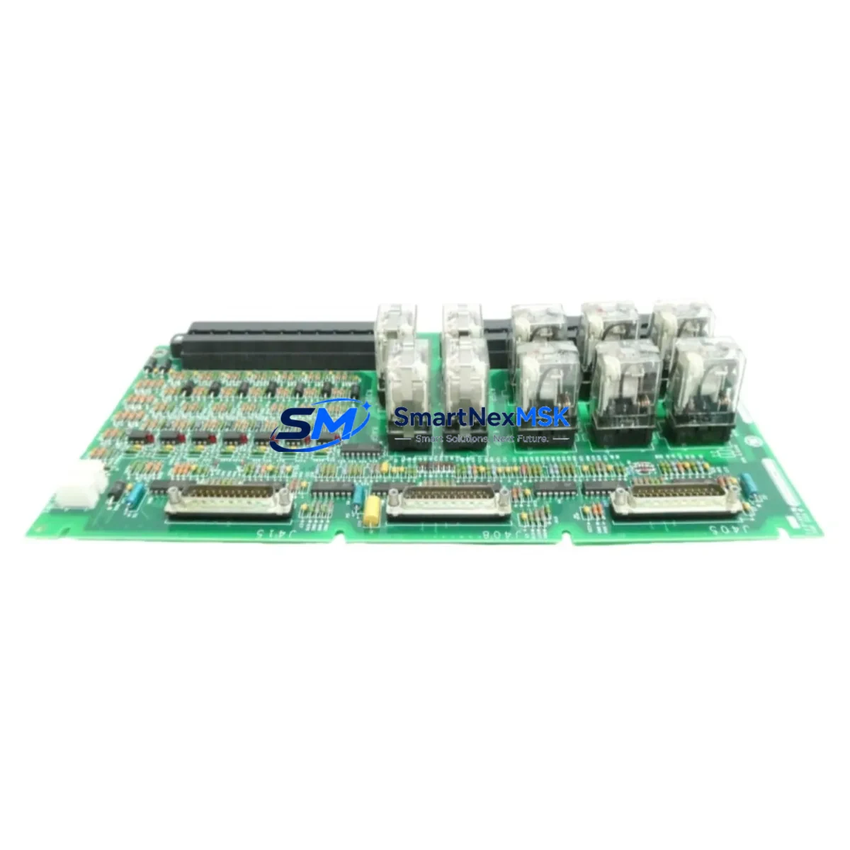
GE IS200ECTBG1A Retrofit-Ready Exciter Terminal Board for Mark VI Control Systems
The GE IS200ECTBG1A is a high-reliability Exciter Contact Terminal Board engineered for the GE Mark VI Turbine Control System platform. Designed to serve as a direct retrofit replacement for aging or discontinued exciter interface boards, the IS200ECTBG1A enables plant engineers and automation integrators to restore full exciter control functionality without requiring a complete control system overhaul. Whether you are managing a gas turbine, steam turbine, or combined-cycle plant, this board provides the electrical interface between the Mark VI controller and the generator excitation system, supporting stable voltage regulation and reactive power control throughout the upgrade process.
In legacy turbine control environments, the exciter terminal board is one of the most frequently replaced components during a Mark VI panel refurbishment. The IS200ECTBG1A is wiring-compatible with the original factory configuration, meaning field technicians can complete the swap without rewiring the exciter cabinet or modifying the existing terminal block layout. Before installation, engineers should verify the power supply rail voltage — typically 28 VDC from the IS200EPBAG1A power supply board — and confirm that the backplane slot assignment matches the original board address configured in the Mark VI Toolbox software. Incorrect slot addressing will prevent the controller from recognizing the new board and may trigger a hardware fault alarm on the IS215UCVEH2A VME controller card.
When planning a retrofit around the IS200ECTBG1A, the terminal wiring from the exciter field current feedback circuit must be carefully documented before removal of the old board. The connector pinout on the IS200ECTBG1A follows the standard Mark VI I/O terminal block convention, and the field wiring — including the AVR (Automatic Voltage Regulator) feedback signal, field current transducer output, and exciter enable relay contacts — should be verified against the original plant wiring diagram. Any deviation in signal polarity or shielding continuity can introduce noise into the exciter control loop, affecting generator terminal voltage stability.
Upgrade Compatibility Table
| Parameter | Details |
|---|---|
| Compatible Platform | GE Mark VI Turbine Control System |
| Board Function | Exciter Contact Terminal Interface |
| Replaces / Upgrades | IS200ECTBG1A (same SKU, refurbished or OEM replacement) |
| Backplane Interface | Mark VI VME-compatible I/O backplane |
| Power Requirement | 28 VDC (supplied via IS200EPBAG1A or equivalent power board) |
| Communication Compatibility | Mark VI internal I/O bus; compatible with IONet Ethernet backbone |
| Installation Type | Direct board swap; no rewiring required under standard configuration |
| Retrofit Recommendation | Verify slot address in Mark VI Toolbox before power-up |
| Commissioning Notes | Confirm AVR feedback signal integrity and exciter enable relay continuity |
| Warranty | 12-Month Warranty included |
Retrofit Planning for Existing Automation Systems
A successful IS200ECTBG1A retrofit begins well before the maintenance window opens. The first step is a full audit of the existing Mark VI panel, including the condition of the IS200VCRCH1B VME card rack, the integrity of the IS200BICLH1A I/O terminal boards sharing the same backplane, and the firmware revision loaded on the IS215UCVEH2A controller. If the plant is running an older Mark VI firmware version, the replacement board may require a firmware compatibility check through GE’s Mark VI Toolbox configuration utility before it can be recognized correctly.
The exciter control loop in a Mark VI system typically involves several interconnected components. The IS200EACFG1A exciter application card works in conjunction with the IS200ECTBG1A to process field current feedback and generate the firing pulses for the static excitation thyristor bridge. If the IS200EACFG1A is also showing signs of degradation — such as intermittent AVR faults or erratic reactive power output — it is strongly recommended to replace both boards during the same outage window to avoid a repeat shutdown. Similarly, the IS200EPBAG1A power supply board should be load-tested before the new terminal board is installed, as an under-voltage condition on the 28 VDC rail can cause the IS200ECTBG1A to fail diagnostics even when the board itself is fully functional.
For plants that are simultaneously upgrading their HMI infrastructure from the legacy GE Cimplicity SCADA platform to a modern OPC-UA-based supervisory system, the IS200ECTBG1A retrofit can be coordinated with the IONet Ethernet communication reconfiguration. The Mark VI’s IONet backbone — connecting the IS215UCVEH2A controller to remote I/O panels — should be verified for packet loss and latency before the new board is commissioned, as communication errors during the exciter initialization sequence can trigger protective trips. If the plant uses a IS200TREGH1B terminal board for generator protection relay interfacing in the same panel, its wiring should be isolated during the IS200ECTBG1A swap to prevent accidental contact with live relay circuits.
Plants operating dual-redundant Mark VI configurations (TMR — Triple Modular Redundancy) must replace the IS200ECTBG1A in all three control paths (R, S, T) to maintain voting logic integrity. Replacing only one board in a TMR system will cause a persistent mismatch alarm and may force the system into simplex operation, reducing fault tolerance. The IS200VCRCH1B card rack provides the physical housing for all three controller paths, and the board swap sequence should follow the plant’s approved hot-standby changeover procedure to avoid a full turbine trip.
Downtime Control During System Migration
Minimizing downtime during an IS200ECTBG1A replacement requires a structured pre-outage preparation protocol. Before the maintenance window, the complete Mark VI configuration — including all I/O assignments, exciter control parameters, AVR setpoints, and alarm thresholds — should be backed up from the Mark VI Toolbox to a secure engineering workstation. This backup ensures that if the new board requires a fresh configuration download, the original control logic can be restored within minutes rather than hours.
During the physical swap, the exciter field breaker should be opened and locked out before any terminal board work begins. The IS200ECTBG1A can be removed and reinstalled without powering down the entire Mark VI panel in some configurations, but this depends on the plant’s specific safety procedures and whether the board is installed in a hot-swap-capable slot. After the new board is seated and the terminal connections are verified, the Mark VI Toolbox should be used to perform a hardware scan to confirm the board is recognized at the correct slot address before the exciter field breaker is reclosed.
Post-installation commissioning should include a step-by-step exciter functional test: verify the AVR auto/manual transfer, confirm field current feedback scaling, check the reactive power droop setting, and validate the under-excitation limiter response. These tests can typically be completed within a two-to-four-hour commissioning window, allowing the unit to return to service within a single planned outage. All test results should be documented and retained as part of the plant’s maintenance record to support future audits and warranty claims under the 12-month warranty coverage provided with the IS200ECTBG1A.
Retrofit Support FAQ
Q1: Is the IS200ECTBG1A a direct drop-in replacement for the original board?
Yes. The IS200ECTBG1A is designed as a direct replacement for the same SKU in GE Mark VI control panels. The board uses the same backplane connector, terminal block layout, and I/O addressing scheme as the original factory-installed unit. No hardware modifications to the panel are required under standard retrofit conditions. However, engineers should verify the board revision level and confirm firmware compatibility using the Mark VI Toolbox before power-up.
Q2: What wiring checks are required before installing the IS200ECTBG1A?
Before installation, verify the continuity and polarity of the AVR feedback signal wiring, the field current transducer output cable, and the exciter enable relay contact wiring. Confirm that all cable shields are properly grounded at the panel end and that no wires have been cross-connected during previous maintenance activities. A wiring verification against the original plant schematic is strongly recommended before the exciter field breaker is reclosed.
Q3: Can the IS200ECTBG1A be used in a TMR (Triple Modular Redundancy) Mark VI system?
Yes, but all three redundant boards in the R, S, and T control paths must be replaced simultaneously to maintain TMR voting logic integrity. Replacing only one board in a TMR configuration will generate a persistent mismatch alarm and may reduce the system to simplex operation. Follow the plant’s approved hot-standby changeover procedure and coordinate the replacement sequence with the control room operator to avoid an unplanned turbine trip.
Q4: What does the 12-month warranty cover, and how is it supported?
The 12-month warranty covers manufacturing defects, component failures under normal operating conditions, and board-level functional failures confirmed by pre-shipment testing. Each IS200ECTBG1A unit undergoes functional testing before dispatch to verify I/O signal integrity, power rail performance, and communication bus compatibility. Warranty claims are supported by SMARTNEXMSK’s technical team, and replacement units can be dispatched from stock to minimize plant downtime. Contact sales@smartnexmsk.com or +86 18259474341 for warranty support and RMA processing.
© 2026 SMARTNEXMSK. All rights reserved.
Original Source: https://smartnexmsk.com
Contact: sales@smartnexmsk.com | +86 18259474341


