GE IS200EPDMG1A Retrofit-Ready Exciter Power Module for Mark VI: Compatible Modernization and Legacy System Upgrade
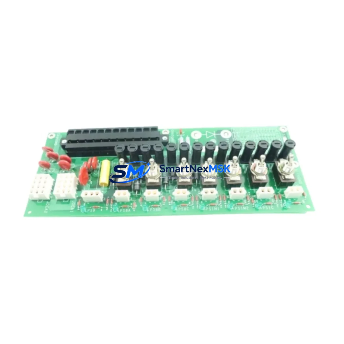
The GE IS200EPDMG1A is an Exciter Power Distribution Module engineered for the GE Mark VI turbine control platform. As aging Mark VI installations approach end-of-support cycles, plant engineers and maintenance teams increasingly rely on verified replacement modules like the IS200EPDMG1A to sustain operational continuity without committing to full DCS overhauls. This module serves as a direct retrofit solution for facilities managing gas turbines, steam turbines, and combined-cycle power generation assets where the original exciter control hardware has become obsolete, difficult to source, or no longer supported under OEM service agreements.
The IS200EPDMG1A interfaces directly with the Mark VI VME-based backplane architecture, distributing regulated power to the exciter control loop and associated I/O subsystems. Its form factor, connector pinout, and firmware compatibility are aligned with the original GE specification, making it a drop-in candidate for most Mark VI cabinets without requiring structural modifications to the control enclosure. Before installation, engineers should verify the existing power supply module — typically an IS200EPSMG1A or equivalent — is delivering within rated voltage tolerances, as degraded upstream power can mask module faults and complicate post-swap commissioning.
During retrofit planning, terminal wiring documentation from the original Mark VI I/O pack configuration should be preserved and cross-referenced against the replacement module’s terminal block layout. In many legacy installations, field wiring was routed through IS200TBCIH1C or IS200TBCIH1BAA terminal boards, and any deviation in wiring sequence must be corrected before energizing the replacement module. Failure to validate terminal mapping is one of the most common causes of extended downtime during exciter module replacements.
Upgrade Compatibility Table
| Parameter | Details |
|---|---|
| SKU / Part Number | IS200EPDMG1A |
| Compatible Platform | GE Mark VI Turbine Control System |
| Module Function | Exciter Power Distribution |
| Backplane Interface | VME-based Mark VI rack |
| Installation Requirement | Direct slot replacement; no rack modification required |
| Communication Compatibility | Mark VI internal I/O bus; compatible with IONet architecture |
| Replacement Recommendation | Verify upstream IS200EPSMG1A power supply output before swap |
| Commissioning Focus | Terminal wiring validation, module address assignment, HMI alarm reset |
| Warranty | 12 Months from date of shipment |
| Outgoing Test | Functional burn-in test performed prior to dispatch |
Retrofit Planning for Existing Automation Systems
A successful IS200EPDMG1A retrofit begins well before the module arrives on site. Maintenance planners should audit the full Mark VI cabinet to identify any co-dependent components that may require simultaneous replacement. In many aging installations, the IS200EPDMG1A failure is symptomatic of broader power distribution degradation affecting adjacent modules such as the IS200VCRCH1B voltage regulator card or the IS200DSPXH1D digital signal processor board. Replacing the exciter power module in isolation without inspecting these related components risks repeat failures within a short operational window.
For facilities running redundant Mark VI configurations — TMR (Triple Modular Redundant) or dual-redundant setups — the replacement sequence must account for the active voting logic. Technicians should coordinate with the control room to confirm which redundant path is being taken offline, and the IS200EPDMG1A swap should be performed on the standby channel first to allow system validation before the primary channel is touched. The IS215VCMIH2C communication module and associated IONet fiber links should remain active throughout the swap to preserve real-time data exchange with the HMI and historian.
Where the existing installation includes a GE Mark VIe migration path, the IS200EPDMG1A may serve as an interim solution while the broader platform upgrade is planned. In such cases, the module’s compatibility with the existing IS200TRLYH1B relay output board and IS200BICLH1C analog input conditioning board should be confirmed to avoid signal chain interruptions during the transition period. Programming engineers should also back up the existing ToolboxST project file and document all I/O assignments, setpoints, and alarm thresholds before any hardware change is executed.
Downtime Control During System Migration
Minimizing unplanned downtime during an IS200EPDMG1A replacement requires a structured pre-outage checklist. Before the maintenance window opens, the replacement module should be bench-tested against a known-good Mark VI rack to confirm firmware revision compatibility and verify that no diagnostic fault codes are present at power-up. This pre-shipment functional test is standard practice and is completed before dispatch.
On-site, the outage sequence should begin with a controlled shutdown of the exciter loop, followed by a full backup of the Mark VI application program using ToolboxST. The IS200EPDMG1A can then be extracted from its slot, and the replacement module inserted with care to align the VME connector without bending pins. After seating, the module address should be confirmed against the rack configuration file before power is restored. HMI screens tied to exciter status — including voltage regulation feedback, field current monitoring, and protection relay status — should be verified to confirm correct data refresh before the unit is returned to service.
For sites where the Mark VI communicates upstream to a DCS or SCADA platform via Modbus or OPC-DA, the communication link should be monitored during the restart sequence to confirm that the IS200EPDMG1A replacement has not introduced any address conflicts or polling timeouts. If the site uses a GE Cimplicity HMI, alarm suppression should be applied selectively during the restart window to prevent nuisance trips from masking genuine fault conditions.
Retrofit Support FAQ
Q: Is the IS200EPDMG1A a direct replacement for the original GE part?
A: Yes. The IS200EPDMG1A is sourced and tested to match the original GE specification for the Mark VI exciter power distribution function. It is compatible with the standard VME backplane slot and does not require firmware re-flashing in most installations. Customers are advised to confirm the hardware revision of their existing rack before ordering.
Q: What wiring checks are required before installation?
A: Terminal block wiring should be documented and verified against the original Mark VI I/O drawing package. Pay particular attention to the power input terminals and any field wiring routed through terminal boards. Incorrect wiring is the leading cause of post-installation faults and can damage the replacement module if not corrected prior to energization.
Q: How is the module tested before shipment?
A: Every IS200EPDMG1A unit undergoes a functional burn-in test on a compatible Mark VI rack prior to dispatch. The test validates power distribution output, internal diagnostics, and communication bus response. A test report is available upon request.
Q: What warranty coverage is provided?
A: All units are covered by a 12-month warranty from the date of shipment. The warranty covers manufacturing defects and functional failures under normal operating conditions. On-site installation support and commissioning guidance are available through our technical team.
© 2026 SMARTNEXMSK. All rights reserved.
Original Source: https://smartnexmsk.com
Contact: sales@smartnexmsk.com | +86 18259474341


