GE IS200JPDBG1A Retrofit-Ready AC Power Distribution Board for Mark VI IS200 Control Systems
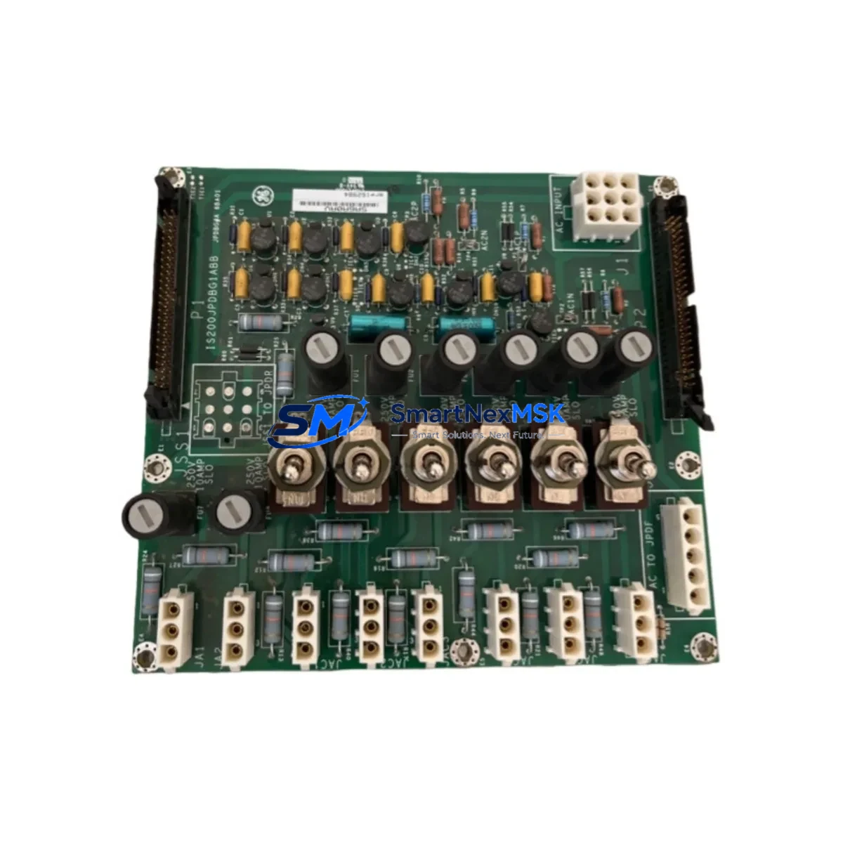
The GE IS200JPDBG1A is an AC Power Distribution Board engineered for the Mark VI IS200 series turbine control platform. As legacy Mark VI systems approach end-of-life support cycles, plant engineers and automation integrators increasingly rely on verified replacement units like the IS200JPDBG1A to sustain operational continuity without committing to a full control system overhaul. This board serves as a direct retrofit solution for facilities running aging Mark VI cabinets where the original power distribution assembly has degraded, failed, or become unavailable through OEM channels.
The IS200JPDBG1A handles AC power routing within the Mark VI control enclosure, distributing conditioned power to downstream I/O boards, communication modules, and processor cards. Its role is foundational: without a functioning power distribution board, the entire control rack loses regulated supply, triggering protective shutdowns and halting turbine or generator operations. For retrofit projects, sourcing a tested IS200JPDBG1A from verified inventory is often the fastest path to restoring system availability — typically faster than waiting on OEM lead times that can stretch 16–26 weeks for discontinued assemblies.
Upgrade Compatibility Table
| Parameter | Details |
|---|---|
| Compatible Platform | GE Mark VI Turbine Control System |
| Compatible Series | IS200 Series (IS200JPDBG1A, IS200JPDBG1ABB) |
| Board Function | AC Power Distribution within Mark VI control enclosure |
| Mounting / Installation | Direct backplane mount; matches original IS200 rack footprint |
| Connector Interface | Compatible with standard Mark VI backplane edge connectors |
| Communication Compatibility | Passive power board; no protocol dependency — compatible with IONet, ARCNET, and Ethernet-based Mark VI variants |
| Replacement Recommendation | Direct drop-in for IS200JPDBG1A and IS200JPDBG1ABB suffix variants |
| Commissioning Notes | Verify AC input voltage range, fuse ratings, and terminal torque specs before energizing |
| Origin | CN (tested and inspected prior to shipment) |
| Warranty | 12-Month Warranty — covers functional failure under normal operating conditions |
Retrofit Planning for Existing Automation Systems
A successful IS200JPDBG1A retrofit begins well before the replacement unit arrives on site. Engineers should start by auditing the existing Mark VI cabinet layout, confirming the rack configuration and identifying all boards currently installed. In a typical Mark VI enclosure, the power distribution board works in close coordination with the IS200TBAAH1A terminal board assembly, which handles field wiring terminations, and the IS200VTURH1BBA VME turbine regulation board, which manages core control logic. Both must remain functional and properly seated during the power board swap.
Before removing the IS200JPDBG1A, document the AC input wiring, including phase assignments and neutral connections, using the plant’s as-built drawings or by tracing the existing terminations. The IS200JPDBG1A feeds regulated power to multiple downstream modules — including I/O boards such as the IS200BIOSH1A and communication interface cards like the IS200ECTBG1A Ethernet communication board. Any interruption to these boards during the swap must be accounted for in the outage plan.
For sites running HMI systems connected to the Mark VI via the IS200DSPXH1A or similar display interface boards, confirm that the HMI screens are placed in manual or bypass mode before de-energizing the rack. This prevents false alarms and protects the integrity of the HMI configuration database. Similarly, if the control system uses an IS200STCIH1A speed and temperature control board, verify that all analog and digital I/O signals are in a safe state before the board is removed.
Power capacity verification is critical. Measure the total load drawn by all installed boards in the rack and confirm the IS200JPDBG1A’s rated output capacity is sufficient. Overloading a replacement power distribution board is a common cause of premature failure in retrofit scenarios. If the rack has been expanded with additional I/O modules since the original installation, a power budget recalculation is mandatory.
For sites where the Mark VI communicates with a DCS or SCADA layer via Modbus, PROFIBUS, or OPC-DA, ensure the communication link is suspended or placed in a degraded-mode fallback before the retrofit begins. This protects the upstream control room from receiving spurious data during the board exchange. After reinstallation, re-establish the communication link and verify that all data points are reading correctly before returning the unit to automatic control.
Downtime Control During System Migration
Minimizing downtime during a Mark VI power board replacement requires a structured pre-outage checklist and a clear rollback plan. Begin by creating a full backup of the Mark VI application program using the GE Toolbox software suite. Store the backup on an isolated engineering workstation — not on the control network — to protect against accidental overwrite. If the site uses a redundant Mark VI configuration with R, S, and T controllers, the retrofit can often be staged to maintain at least one active control path throughout the process, significantly reducing the risk of a full process shutdown.
During the physical swap, use anti-static precautions and handle the IS200JPDBG1A by its edges. Inspect the backplane connectors for bent pins or corrosion before seating the replacement board. After installation, apply power incrementally if the cabinet design permits, monitoring each voltage rail with a calibrated multimeter before enabling the full load. This staged energization approach catches wiring errors before they can damage downstream boards.
Once the board is powered and the Mark VI controller has completed its self-diagnostic cycle, verify that all I/O boards are recognized by the controller and that no hardware fault codes are active. Reload the application program from the backup if the controller prompts for a configuration download. Confirm that all analog inputs, digital outputs, and communication links are operating within expected parameters before releasing the unit back to automatic control. A structured post-retrofit test record — covering power rail voltages, I/O point verification, and communication link status — provides the documentation needed for plant maintenance records and regulatory compliance.
Retrofit Support FAQ
Q: Is the IS200JPDBG1A a direct replacement for all IS200JPDBG1ABB suffix variants?
A: Yes. The IS200JPDBG1A and IS200JPDBG1ABB are functionally equivalent and share the same backplane footprint, connector layout, and power distribution architecture. The suffix difference reflects a minor revision level and does not affect drop-in compatibility within the Mark VI IS200 series rack.
Q: What pre-installation checks are required before fitting the replacement board?
A: Verify the AC input voltage range matches your site supply, inspect all terminal connections for correct torque and insulation integrity, confirm fuse ratings match the original specification, and ensure the backplane connectors are clean and undamaged. A power budget check is recommended if additional I/O boards have been added to the rack since the original installation.
Q: How is the board tested before shipment?
A: Each IS200JPDBG1A unit undergoes functional power-on testing and visual inspection prior to dispatch. Test records are available on request. The board is shipped with ESD-protective packaging to prevent transit damage.
Q: What does the 12-month warranty cover?
A: The 12-month warranty covers functional failure of the IS200JPDBG1A under normal operating conditions. It does not cover damage resulting from incorrect installation, overvoltage events, or physical mishandling. Warranty claims are processed via direct contact with our technical support team, and replacement or repair is provided at no additional cost within the warranty period.
© 2026 SMARTNEXMSK. All rights reserved.
Original Source: https://smartnexmsk.com
Contact: sales@smartnexmsk.com | +86 18259474341


