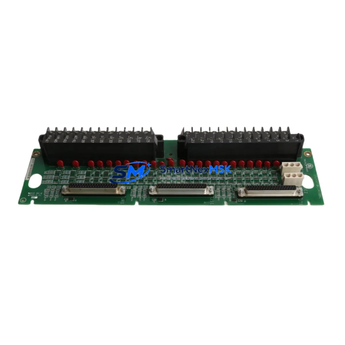
GE IS200TBCIS2C Retrofit-Ready Termination Board for Mark VI Control Systems
The GE IS200TBCIS2C is a contact input termination board engineered for the GE Mark VI turbine control platform. As legacy Mark VI installations approach end-of-life or require capacity expansion, the IS200TBCIS2C serves as a critical interface component enabling smooth migration from older Mark V and early Mark VI configurations to current-generation control architectures. Whether you are replacing a failed board, upgrading a deteriorating control cabinet, or executing a planned system modernization, the IS200TBCIS2C provides the electrical and mechanical compatibility required to maintain operational continuity with minimal disruption to existing field wiring.
Sourced directly from verified industrial supply channels, each unit undergoes pre-shipment functional verification covering contact input signal integrity, terminal block continuity, and backplane connector alignment. All units are supplied with a 12-month warranty covering manufacturing defects and functional failures under normal operating conditions. Stock is maintained for immediate dispatch, supporting both emergency breakdown replacements and scheduled maintenance windows.
Upgrade Compatibility Table
| Parameter | Details |
|---|---|
| SKU / Part Number | IS200TBCIS2C |
| Compatible Platform | GE Mark VI Turbine Control System |
| Board Function | Contact Input Termination Board |
| Replaces / Upgrades From | IS200TBCIS2A, IS200TBCIS2B (earlier revisions); Mark V TCCA/TCCB contact input boards |
| Backplane Interface | Mark VI standard VME-style backplane connector; verify slot assignment before installation |
| Terminal Block Compatibility | Standard Mark VI field terminal wiring; no re-termination required for direct replacement |
| Communication Protocol | Internal Mark VI I/O bus; compatible with IONET and ARCNET control network configurations |
| Power Requirements | Supplied via Mark VI backplane; confirm rack power budget before adding modules |
| Installation Requirement | Mark VI I/O rack with available slot; module address configuration via ToolboxST software |
| Retrofit Recommendation | Suitable for direct slot replacement; verify firmware revision compatibility in ToolboxST |
| Commissioning Focus | Contact input signal mapping, I/O forcing test, HMI alarm point verification |
| Warranty | 12 Months — covers manufacturing defects and functional failures under normal use |
Retrofit Planning for Existing Automation Systems
A successful IS200TBCIS2C retrofit begins well before the board arrives on site. Engineers should start by auditing the existing Mark VI rack configuration using ToolboxST, GE’s configuration and diagnostic software for the Mark VI platform. This audit identifies the current slot assignments, I/O module addresses, and any firmware dependencies that may affect drop-in compatibility. In many installations, the IS200TBCIS2C shares a rack with companion modules such as the IS200TBCIS1C analog input termination board, the IS200VTURH1BEE turbine control board, and the IS215VCMIH2C VME communication interface module — all of which must remain operational during the swap.
Field wiring connected to the contact input terminals should be documented and photographed before removal. The IS200TBCIS2C uses the standard Mark VI terminal block layout, meaning existing field cables from limit switches, relay contacts, and discrete sensors can typically be reconnected without modification. However, engineers should verify terminal torque specifications and inspect for any corrosion or insulation degradation that may have developed over years of service.
Power budget verification is essential when adding or replacing modules in an existing Mark VI rack. The rack’s IS200EPBAG1A power supply board or equivalent must have sufficient headroom to support the IS200TBCIS2C alongside other installed modules such as the IS200TBAIH2C analog input board and any IS200TBQCH1C thermocouple input termination boards. Overloading the rack power supply is a common cause of intermittent faults during post-retrofit commissioning.
For sites migrating from Mark V to Mark VI, the IS200TBCIS2C plays a role in the I/O expansion strategy. Mark V contact input signals previously handled by TCCA or TCCB boards must be remapped to the Mark VI I/O address space. This remapping is performed in ToolboxST and must be validated against the existing application code before the new board is brought online. Communication links between the Mark VI controller and upstream DCS or SCADA systems — whether via IONET, Modbus, or OPC — should be tested in simulation mode before live cutover to confirm that contact input states are correctly reflected in the control room HMI.
Sites using GE’s IS200SRLYH1B relay output board or IS200TTURH1BEE turbine terminal board in the same control cabinet should coordinate the IS200TBCIS2C replacement with any planned maintenance on those adjacent modules to minimize total cabinet downtime. Programming cables such as the IC693CBL316 or equivalent Mark VI serial interface cables should be on hand for on-site ToolboxST diagnostics during commissioning.
Downtime Control During System Migration
Minimizing downtime during an IS200TBCIS2C replacement requires a structured pre-outage preparation protocol. Before the planned maintenance window, engineers should export the complete ToolboxST project file and create a verified backup of the current Mark VI application, including all I/O configurations, alarm setpoints, and sequence logic. This backup serves as the recovery baseline if any unexpected compatibility issue arises during the swap.
Where the process permits, contact inputs served by the IS200TBCIS2C should be placed in a forced or bypassed state within the control logic prior to board removal. This prevents spurious alarms or protective trips from propagating to the turbine control sequence during the physical swap. The forced states must be clearly documented and systematically released during the post-installation verification phase.
Physical replacement of the IS200TBCIS2C is typically completed within 30 to 60 minutes for a prepared team. After seating the new board and reconnecting field terminals, the ToolboxST download procedure re-establishes the module address and I/O mapping. Contact input states should be verified point-by-point against the field device status before releasing any forced conditions. HMI screens displaying contact input-derived status indicators — such as valve position feedback, breaker status, and interlock conditions — should be reviewed to confirm correct signal representation before returning the unit to automatic control.
For critical turbine applications where zero unplanned downtime is the objective, maintaining a spare IS200TBCIS2C in the site’s strategic spare parts inventory is strongly recommended. Given the age profile of many Mark VI installations, lead times for new manufacture can be extended, making pre-positioned stock the most reliable downtime mitigation strategy.
Retrofit Support FAQ
Q: Is the IS200TBCIS2C a direct drop-in replacement for the IS200TBCIS2A and IS200TBCIS2B?
A: In most cases, yes. The IS200TBCIS2C is a later revision of the same board family and is designed to be backward compatible with earlier IS200TBCIS2A and IS200TBCIS2B installations. However, you should verify the firmware revision in ToolboxST and confirm that the slot address assignment is unchanged before powering up the replacement board.
Q: What commissioning steps are required after installing the IS200TBCIS2C?
A: After physical installation, perform a ToolboxST download to assign the module address and load the I/O configuration. Conduct a point-by-point contact input verification by actuating each field device and confirming the correct state change in the ToolboxST I/O diagnostic view and on the HMI. Release any forced I/O states in sequence and confirm that no spurious alarms are generated before returning to automatic operation.
Q: Can the IS200TBCIS2C be used in a Mark V to Mark VI migration project?
A: Yes. The IS200TBCIS2C is a Mark VI native module and is commonly used in Mark V to Mark VI migration projects to re-terminate existing field wiring for contact inputs. The migration requires remapping the I/O addresses in ToolboxST and updating the application code to reference the new module locations. GE’s migration documentation and a qualified controls engineer should be consulted for the full migration procedure.
Q: What does the 12-month warranty cover?
A: The 12-month warranty covers manufacturing defects and functional failures under normal operating conditions from the date of shipment. Each unit is pre-tested before dispatch to verify contact input signal integrity and backplane connector function. Warranty claims are processed promptly with replacement units dispatched from available stock to minimize your system downtime.
© 2026 SMARTNEXMSK. All rights reserved.
Original Source: https://smartnexmsk.com
Contact: sales@smartnexmsk.com | +86 18259474341


