GE IS210BPPCH1AEC Retrofit-Ready I/O Processor for Mark VIe Control Systems
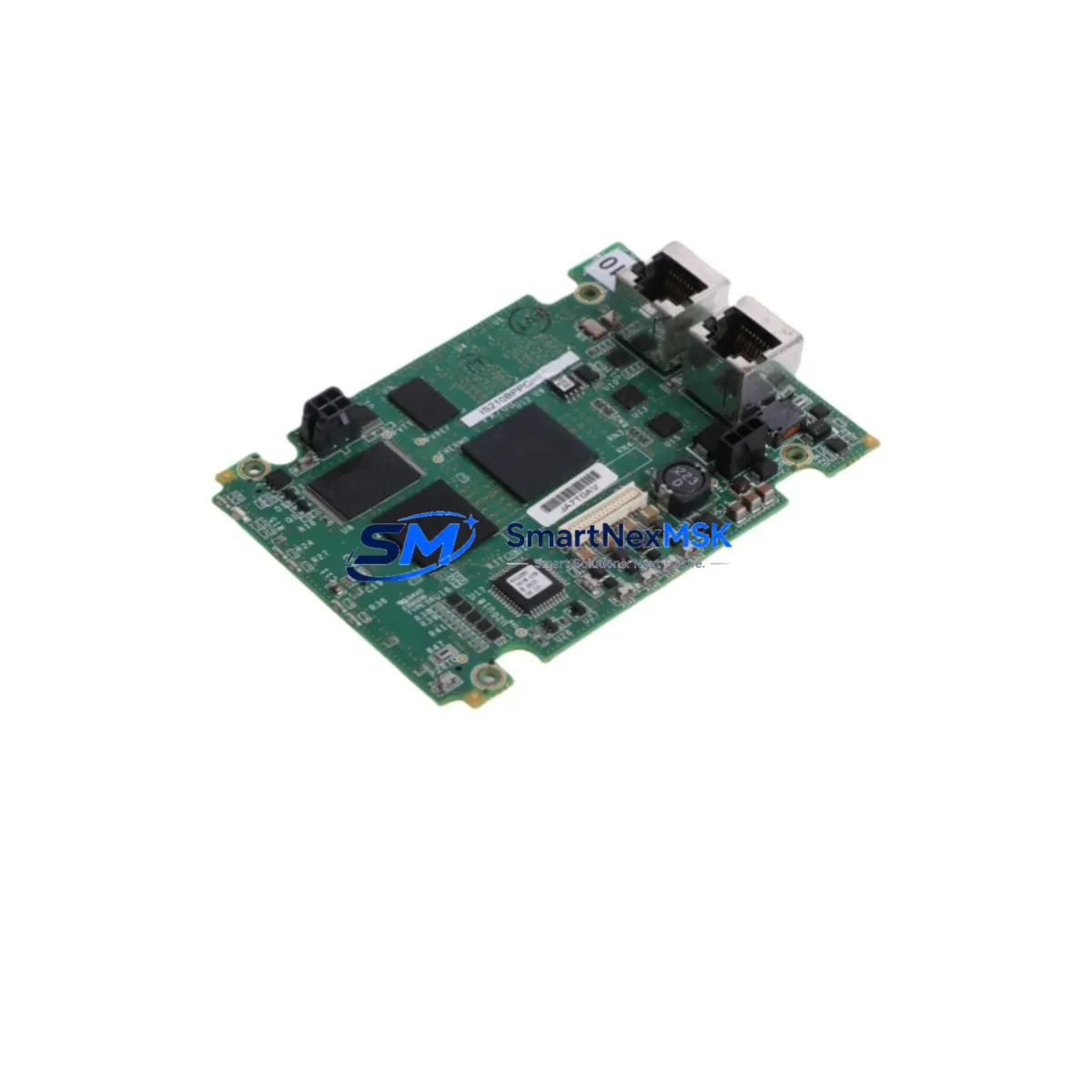
The GE IS210BPPCH1AEC is a high-reliability I/O Pack Processor Board engineered for the GE Mark VIe distributed control platform, widely deployed across gas turbine, steam turbine, and combined-cycle power generation facilities. As legacy Mark VI and early Mark VIe installations approach end-of-support milestones, the IS210BPPCH1AEC has become a critical retrofit component for engineers tasked with extending operational life, restoring failed control loops, and executing phased modernization programs without full system replacement.
This board serves as the local processing core within the Mark VIe I/O Pack architecture, managing real-time signal conditioning, diagnostic reporting, and communication with the IS215VCMIH2C VME Controller Module over the IONet Ethernet backbone. When an existing IS210BPPCH1AEC fails or reaches its service limit, replacement must be carefully coordinated to preserve turbine control continuity, protect existing ladder logic and function block programs, and avoid unplanned outages.
Upgrade Compatibility Table
| Parameter | Details |
|---|---|
| Compatible Platform | GE Mark VIe, Mark VI (with adapter verification) |
| Replaces / Supersedes | IS210BPPCH1A, IS210BPPCH1AEB (earlier revisions) |
| Backplane Interface | Mark VIe I/O Pack connector — verify J1/J2 pin alignment before installation |
| Communication Protocol | IONet (100 Mbps Ethernet), PROFIBUS DP (via gateway modules) |
| Power Supply Requirement | 24 VDC from I/O Pack power rail; verify IS200EPSMG1A or equivalent PSU capacity |
| Module Address Config | DIP switch / ToolboxST software assignment — must match original rack address |
| Firmware Compatibility | Confirm ToolboxST project firmware revision before swapping |
| Installation Type | Hot-swap capable with proper sequence; cold-swap recommended for first-time retrofit |
| Debugging Tool | GE ToolboxST, Mark VIe Diagnostic Viewer |
| Warranty | 12 Months — covers manufacturing defects, functional failure, and DOA replacement |
Retrofit Planning for Existing Automation Systems
A successful IS210BPPCH1AEC retrofit begins well before the module arrives on-site. Engineers should first audit the existing I/O Pack rack configuration, documenting the slot position, wiring terminal assignments, and the current firmware version recorded in ToolboxST. The IS200IOCIH2C I/O Controller Interface board and the IS215VCMIH2C VME Controller must both be confirmed compatible with the replacement board revision to avoid communication faults on the IONet segment.
Terminal wiring on the associated IS200TBCIH1C terminal board should be photographed and labeled before disconnection. Each analog input, digital output, and RTD channel must be mapped against the original I/O configuration in the ToolboxST project file. If the plant is running a mixed Mark VI / Mark VIe architecture, verify that the IS200DSPXH1D DSP board in the adjacent rack is not sharing interrupt lines that could be disrupted during the swap.
Power budget verification is essential: the IS200EPSMG1A power supply module feeding the I/O Pack rail must have sufficient headroom to support the replacement board during initialization. If the rack also houses an IS210AEBIH3BEC Analog I/O board or an IS200TRLYH1C Relay Output board, total rail current draw must be recalculated. Communication continuity on the PROFIBUS DP segment — typically managed through a IS200PDIOH1C PROFIBUS gateway — should be verified post-swap using a PROFIBUS analyzer before returning the turbine to automatic control.
For facilities migrating from Mark VI to Mark VIe, the IS210BPPCH1AEC also plays a role in I/O expansion projects where new IS210AEBIH3BEC analog boards are being added to extend measurement coverage. In these cases, rack addressing must be reassigned in ToolboxST and the HMI tag database updated to reflect new I/O point addresses before commissioning.
Downtime Control During System Migration
Minimizing turbine downtime during an IS210BPPCH1AEC replacement requires a structured pre-outage preparation protocol. Before the planned maintenance window, the ToolboxST project should be exported and backed up, including all function block diagrams, sequence logic, and alarm setpoints. The replacement board should be bench-tested and confirmed powered-on with correct firmware before being brought to the control room.
During the swap, the Mark VIe controller should be placed in manual override where process conditions allow, ensuring that critical control loops — including fuel valve positioning, exhaust temperature monitoring, and vibration trip logic — remain under operator supervision. After physical installation, the board must be assigned its original module address via ToolboxST before the controller is returned to automatic mode. A full I/O diagnostic scan should be executed to confirm all channels are reporting correctly, followed by a communications health check on the IONet segment to verify no packet loss or latency anomalies exist before releasing the unit to operations.
Our pre-shipment testing protocol ensures every IS210BPPCH1AEC is powered, initialized, and functionally verified before dispatch, reducing the risk of DOA failures and keeping your maintenance window on schedule.
Retrofit Support FAQ
Q1: Is the IS210BPPCH1AEC a direct drop-in replacement for earlier IS210BPPCH1A and IS210BPPCH1AEB revisions?
In most cases, yes. The H1AEC revision is backward-compatible with H1A and H1AEB in standard Mark VIe I/O Pack racks. However, firmware version alignment in ToolboxST should be confirmed before installation, as certain rack configurations may require a project download after the swap.
Q2: What wiring changes are required when replacing the IS210BPPCH1AEC?
The IS210BPPCH1AEC itself does not connect directly to field wiring — terminal connections are made at the associated IS200TBCIH1C terminal board, which remains in place during the swap. No field rewiring is required if the terminal board is undisturbed. Verify that all terminal screws are torqued to specification after the board is reseated.
Q3: How is module addressing configured after installation?
Module address assignment is performed through GE ToolboxST software. The replacement board must be assigned the same rack slot address as the original to ensure the Mark VIe controller recognizes it without requiring a full project re-download. Confirm the address in the I/O Pack configuration tree before returning the system to automatic control.
Q4: What does the 12-month warranty cover?
The 12-month warranty covers manufacturing defects, functional failure under normal operating conditions, and dead-on-arrival (DOA) units. Each board is tested prior to shipment. Warranty claims are processed with priority turnaround to minimize impact on plant operations. Contact sales@smartnexmsk.com for RMA procedures.
© 2026 SMARTNEXMSK. All rights reserved.
Original Source: https://smartnexmsk.com
Contact: sales@smartnexmsk.com | +86 18259474341


