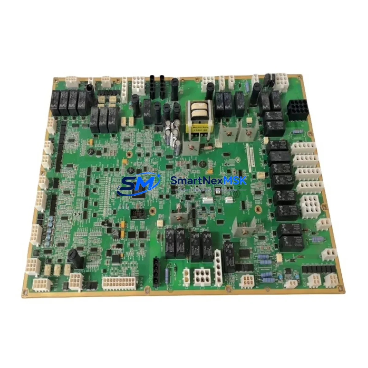
GE IS210WETBH1A Retrofit-Ready Terminal Board for Mark VIe Control Systems
The GE IS210WETBH1A is a high-reliability excitation terminal board engineered for the Mark VIe turbine control platform. As legacy Mark V and Mark VI installations reach end-of-service life, the IS210WETBH1A serves as a critical interface component in planned retrofit programs, enabling engineers to modernize excitation control wiring without redesigning the entire control cabinet. Whether you are replacing a failed board, upgrading a deteriorating Mark VI excitation loop, or migrating from an older DSPX or DSPC-based excitation controller, the IS210WETBH1A provides the terminal density, signal conditioning, and backplane compatibility required for a smooth transition.
This board is fully compatible with the Mark VIe distributed control architecture and is designed to mount directly into the standard Mark VIe I/O rack. It interfaces with the VCMI or VCRC controller cards via the standard Mark VIe backplane connector, eliminating the need for custom wiring adapters in most retrofit scenarios. Engineers migrating from Mark V systems should verify the terminal mapping against the original TCEA or TCEB excitation terminal boards, as signal assignments may differ between generations. A wiring conversion table is strongly recommended before field installation.
Upgrade Compatibility Table
| Parameter | Details |
|---|---|
| Compatible Platform | GE Mark VIe Turbine Control System |
| Replaces / Upgrades From | Mark V TCEA/TCEB, Mark VI IS200 series excitation boards |
| Backplane Interface | Standard Mark VIe I/O rack backplane connector |
| Communication Compatibility | IONet (Mark VIe native Ethernet-based I/O network) |
| Installation Requirement | Mark VIe I/O rack; verify slot address assignment in ToolboxST |
| Terminal Wiring | Screw-terminal field wiring; verify conductor gauge compatibility |
| Retrofit Recommendation | Replace alongside IS200EACAH1A or IS200ESELH1A for full excitation loop upgrade |
| Commissioning Focus | Module address configuration, IONet node assignment, excitation loop calibration |
| Warranty | 12-Month Warranty — covers functional defects under normal operating conditions |
Retrofit Planning for Existing Automation Systems
A successful IS210WETBH1A retrofit begins well before the board arrives on site. The first step is a thorough audit of the existing excitation control loop, including the power supply capacity of the Mark VIe I/O rack. The IS215 power supply modules feeding the rack must be verified to support the additional load introduced by the new terminal board. If the existing IS215UCVEH1A or IS215UCVFH1A power supply is already operating near capacity, a parallel supply or replacement should be planned as part of the same outage window.
Terminal wiring is the most labor-intensive aspect of any excitation board retrofit. The IS210WETBH1A uses a screw-terminal field wiring interface, and engineers should prepare a point-to-point wiring schedule derived from the original Mark V or Mark VI as-built drawings. Pay particular attention to the AVR (Automatic Voltage Regulator) feedback signals, field current sensing inputs, and PT (Potential Transformer) voltage inputs, as these are the most common sources of commissioning errors. Where the original system used a DSPX or DSPC excitation controller, the analog signal scaling may need to be reconfigured in ToolboxST to match the new board’s input range.
For sites running a dual-redundant excitation configuration, the IS210WETBH1A retrofit should be coordinated with the replacement of the companion IS200EACAH1A excitation application card and the IS200ESELH1A excitation selector card. Replacing these three components together ensures that the redundancy logic, voting architecture, and IONet communication links are all operating on matched firmware and hardware revisions. Mismatched revisions between the terminal board and the application card are a known source of intermittent faults in Mark VIe excitation systems.
HMI screen updates are another consideration that is frequently overlooked during excitation retrofits. If the plant runs a GE Cimplicity or iFIX SCADA system, the excitation status displays, alarm setpoints, and trend tags may need to be remapped to reflect the new IONet node address assigned to the IS210WETBH1A. Coordinate with the controls engineer responsible for the HMI configuration before the outage to avoid post-startup alarm floods. Similarly, if the site uses a GE Mark VIe UCSC or UCVG controller card as the primary turbine controller, verify that the IONet configuration file in ToolboxST correctly reflects the new board’s slot and node assignments before downloading the updated configuration.
Communication link verification is essential before returning the unit to service. The IS210WETBH1A communicates over IONet, GE’s proprietary Ethernet-based I/O network used throughout the Mark VIe platform. Confirm that the IONet switch — typically a managed industrial Ethernet switch installed in the control cabinet — has sufficient port capacity and that the network topology matches the ToolboxST configuration. If the retrofit is part of a broader migration from Mark V to Mark VIe, the legacy ARCNET-based I/O network used by Mark V will need to be fully decommissioned and replaced with IONet infrastructure, including new cabling and switch hardware.
Downtime Control During System Migration
Minimizing unplanned downtime is the primary operational constraint in any excitation board retrofit. The recommended approach is to pre-stage the IS210WETBH1A in the workshop, configure its IONet node address and slot assignment in ToolboxST offline, and perform a bench-level functional test before the scheduled outage window. This pre-commissioning step can reduce on-site installation time by 40–60% and significantly lowers the risk of configuration errors discovered during live commissioning.
Before removing the existing excitation terminal board, capture a full backup of the Mark VIe controller configuration using ToolboxST, including all I/O assignments, calibration constants, and alarm setpoints. Store this backup on a secure engineering workstation and verify its integrity before proceeding. If the site uses a GE Mark VIe UCSC controller, also export the current diagnostic log to establish a pre-retrofit baseline for post-startup comparison.
During the physical swap, label all field wiring before disconnection and photograph the terminal block layout. Reconnect wiring to the IS210WETBH1A according to the prepared wiring schedule, and perform a continuity check on all critical excitation signals before powering up the rack. After power-up, use ToolboxST to verify that the board is recognized on the IONet network and that all I/O points are reading correctly before transferring control back to the excitation loop. A staged return-to-service — first in manual excitation control, then in automatic — is strongly recommended to protect the generator and transformer during the initial post-retrofit period.
All units supplied by SMARTNEXMSK are tested prior to shipment and covered by a 12-month warranty against functional defects. Inventory is maintained in stock for fast dispatch, supporting both planned outage schedules and emergency replacement requirements.
Retrofit Support FAQ
Q: Is the IS210WETBH1A a direct drop-in replacement for the IS200 series excitation terminal boards?
A: The IS210WETBH1A is designed for the Mark VIe platform and shares the same backplane interface standard as other IS210/IS200 series boards. However, terminal wiring assignments and IONet node configuration must be verified against your specific system drawing package before installation. It is not a plug-and-play replacement for Mark V TCEA/TCEB boards without wiring adaptation.
Q: What commissioning steps are required after installing the IS210WETBH1A?
A: After physical installation, you must assign the correct IONet node address and slot number in ToolboxST, download the updated configuration to the Mark VIe controller, verify all I/O point readings, and perform an excitation loop calibration check. HMI tag remapping may also be required if the IONet node address has changed from the previous configuration.
Q: Can the IS210WETBH1A be used in a redundant excitation configuration?
A: Yes. The IS210WETBH1A supports redundant excitation architectures when paired with the appropriate IS200EACAH1A excitation application card and IS200ESELH1A excitation selector card. Ensure all components are on matched hardware and firmware revisions to maintain redundancy integrity.
Q: What does the 12-month warranty cover, and how is it claimed?
A: The 12-month warranty covers functional defects arising under normal operating conditions. It does not cover damage resulting from incorrect installation, overvoltage events, or physical mishandling. To initiate a warranty claim, contact SMARTNEXMSK with the order reference number, a description of the fault, and photographic evidence of the installation. Replacement or repair will be arranged promptly.
© 2026 SMARTNEXMSK. All rights reserved.
Original Source: https://smartnexmsk.com
Contact: sales@smartnexmsk.com | +86 18259474341


