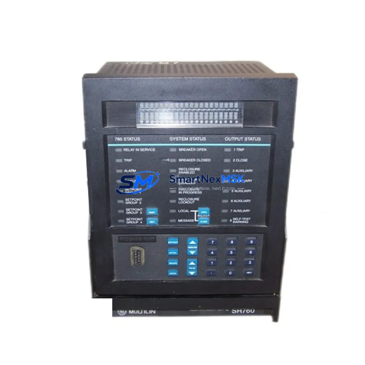
GE SR760 760-P1-G1-S1-HI-A20-R Retrofit-Ready Feeder Management Relay for SR Series Control Systems
The GE SR760 760-P1-G1-S1-HI-A20-R is a microprocessor-based feeder management relay engineered for seamless integration into existing SR Series protection and control architectures. Designed to address the growing demand for discontinued-part replacement and legacy system modernization, this unit delivers full backward compatibility with GE’s SR Series relay platform while meeting the reliability standards required in industrial power distribution, utility substations, and process plant feeder circuits.
For facilities operating aging GE SR Series protection panels, sourcing a verified drop-in replacement for the SR760 is critical to maintaining system continuity. The 760-P1-G1-S1-HI-A20-R variant specifies a particular combination of I/O configuration, high-impedance input option, and analog output range that must be matched precisely during procurement. Before installation, engineers should confirm the existing panel’s power supply voltage (typically 125 Vdc or 120 Vac), verify terminal block wiring compatibility against the original SR760 wiring diagram, and check that the rear-panel communication port assignment aligns with the site’s SCADA or DCS integration requirements.
In retrofit projects where the original SR760 is being replaced due to end-of-life status, the migration process typically involves re-using the existing relay settings file exported from the GE EnerVista SR Series software. Settings files should be validated against the firmware version of the replacement unit before upload. If the replacement unit carries a newer firmware revision, a settings conversion step may be required to ensure that protection element pickup values, time-dial curves, and output relay assignments are preserved without unintended changes.
Upgrade Compatibility Table
| Parameter | Detail |
|---|---|
| Model | GE SR760 760-P1-G1-S1-HI-A20-R |
| Series | GE SR Series Feeder Management Relay |
| Replacement For | GE SR760 (discontinued variants), legacy SR Series feeder relays |
| Mounting | Standard 19″ rack / panel flush mount, compatible with original SR760 cutout |
| Communication Ports | RS-485 (Modbus RTU); optional DNP3 / IEC 60870-5-101 per order code |
| Communication Compatibility | Compatible with existing Modbus RTU SCADA wiring; verify baud rate and parity settings |
| Power Supply Input | Confirm site supply: 85–264 Vac / 88–300 Vdc (wide-range model) |
| I/O Configuration | P1 base I/O; G1 ground fault; S1 sensitive ground; HI high-impedance input; A20 analog output 4–20 mA |
| Installation Requirement | Verify terminal torque specs; re-use existing CT/VT wiring where rated |
| Commissioning | Upload validated settings file via EnerVista SR Series software; perform secondary injection test |
| Retrofit Recommendation | Direct drop-in for SR760 same-variant; settings conversion required for cross-variant migration |
| Warranty | 12-Month Warranty — covers manufacturing defects; includes pre-shipment functional test report |
Retrofit Planning for Existing Automation Systems
A successful SR760 retrofit begins well before the replacement unit arrives on site. The project team should pull the existing panel drawings and confirm the relay’s role within the feeder protection scheme — whether it operates as a primary feeder relay, a backup overcurrent element, or part of a bus differential scheme coordinated with upstream GE SR750 or GE SR735 relays. Understanding this coordination context determines which protection elements must be re-verified after the swap.
On the hardware side, the SR760’s rear terminal block uses a standard GE SR Series connector arrangement. In most installations, the existing CT secondary wiring, VT secondary wiring, and control power cabling can be re-used without modification, provided the cable insulation and terminal lugs are in serviceable condition. The GE SR Series rack or chassis — including the backplane and any associated GE SR Series communication modules — typically remains in place during a like-for-like relay replacement, which significantly reduces installation time and eliminates the need to re-engineer the panel layout.
Where the retrofit involves migrating from an older SR760 variant to the 760-P1-G1-S1-HI-A20-R, engineers must pay particular attention to the analog output wiring. The A20 suffix designates a 4–20 mA analog output channel used for metering or SCADA integration. If the original relay did not include this output, the corresponding wiring and receiving instrument must be added to the scope. Similarly, the HI (high-impedance) input option requires dedicated wiring to the high-impedance fault detection circuit; this should be verified against the site’s earth fault protection philosophy before commissioning.
For sites running GE EnerVista SR Series software on a Windows-based engineering workstation, the settings upload process is straightforward: connect via the front RS-232 port or rear RS-485 port, open the validated settings file, and download to the relay. After download, perform a settings readback to confirm integrity. Secondary injection testing using a relay test set — such as a OMICRON CMC or Megger SMRT — should cover all active protection elements, including phase overcurrent (50/51), ground overcurrent (50N/51N), and any directional elements (67/67N) enabled in the settings file. The GE SR Series programming cable and EnerVista software license should be confirmed available on site before scheduling the outage window.
Downtime Control During System Migration
Minimizing downtime during an SR760 replacement requires a structured outage plan. The recommended approach is to prepare the replacement relay fully before the outage begins: load and verify the settings file, confirm firmware version compatibility, and complete all pre-shipment documentation review. On the day of the outage, the sequence should follow: isolate the feeder circuit, de-energize the relay panel, remove the existing SR760, install the 760-P1-G1-S1-HI-A20-R, reconnect all terminals per the verified wiring schedule, restore control power, and perform a rapid functional check before re-energizing the feeder.
For critical feeders where even a brief outage is operationally sensitive, a parallel commissioning approach can be used: install the replacement relay in a temporary test position, complete all settings verification and secondary injection testing offline, then execute the final swap during a planned maintenance window. This approach is particularly effective in process plants where the feeder supplies continuous-process loads and the GE SR Series protection scheme is integrated with a DCS or safety instrumented system (SIS).
Protecting the original program logic is straightforward with GE EnerVista SR Series software — export the full settings file before any work begins and store it in the project document management system. If the site uses a GE UR Series or Multilin Series relay alongside the SR760 in the same protection panel, ensure that inter-relay communication links (GOOSE or hardwired trip signals) are tested as part of the commissioning scope. Maintaining field control continuity throughout the migration — including HMI screen updates to reflect the new relay’s Modbus register map if any addresses have changed — is essential to avoiding nuisance alarms or missed trip signals after the relay is returned to service.
Retrofit Support FAQ
Q1: Is the GE SR760 760-P1-G1-S1-HI-A20-R a direct drop-in replacement for my existing SR760?
A: For the same order-code variant, yes — the physical dimensions, terminal layout, and communication interface are identical to the original SR760. If your existing relay carries a different variant suffix (e.g., different I/O or communication options), a wiring and settings review is required before installation. Our technical team can assist with cross-variant compatibility assessment prior to shipment.
Q2: What commissioning steps are required after installation?
A: After installing the relay and reconnecting all terminals, upload the validated settings file using GE EnerVista SR Series software. Perform a settings readback to confirm integrity, then conduct secondary injection testing on all active protection elements. Verify analog output (4–20 mA) calibration if the A20 channel is in use. Finally, confirm Modbus communication with the SCADA or DCS before returning the feeder to service.
Q3: How do I verify wiring compatibility before the outage?
A: Compare the existing panel wiring schedule against the SR760 760-P1-G1-S1-HI-A20-R terminal diagram. Key checks include CT/VT secondary circuit continuity, control power polarity, output relay wiring to trip coils and alarms, and RS-485 communication cable shielding and termination. Any discrepancies should be resolved in the pre-outage engineering review.
Q4: What does the 12-Month Warranty cover?
A: The 12-month warranty covers manufacturing defects in materials and workmanship from the date of shipment. Each unit undergoes a pre-shipment functional test, and a test report is available upon request. Warranty claims are processed promptly — contact our sales team with the order reference and a description of the fault. Units damaged by incorrect installation, overvoltage, or unauthorized modification are excluded from warranty coverage.
© 2026 SMARTNEXMSK. All rights reserved.
Original Source: https://smartnexmsk.com
Contact: sales@smartnexmsk.com | +86 18259474341


