Honeywell 10005/0/3 Retrofit-Ready DCS Communication Module: Compatible Modernization for TDC 3000 Control Systems
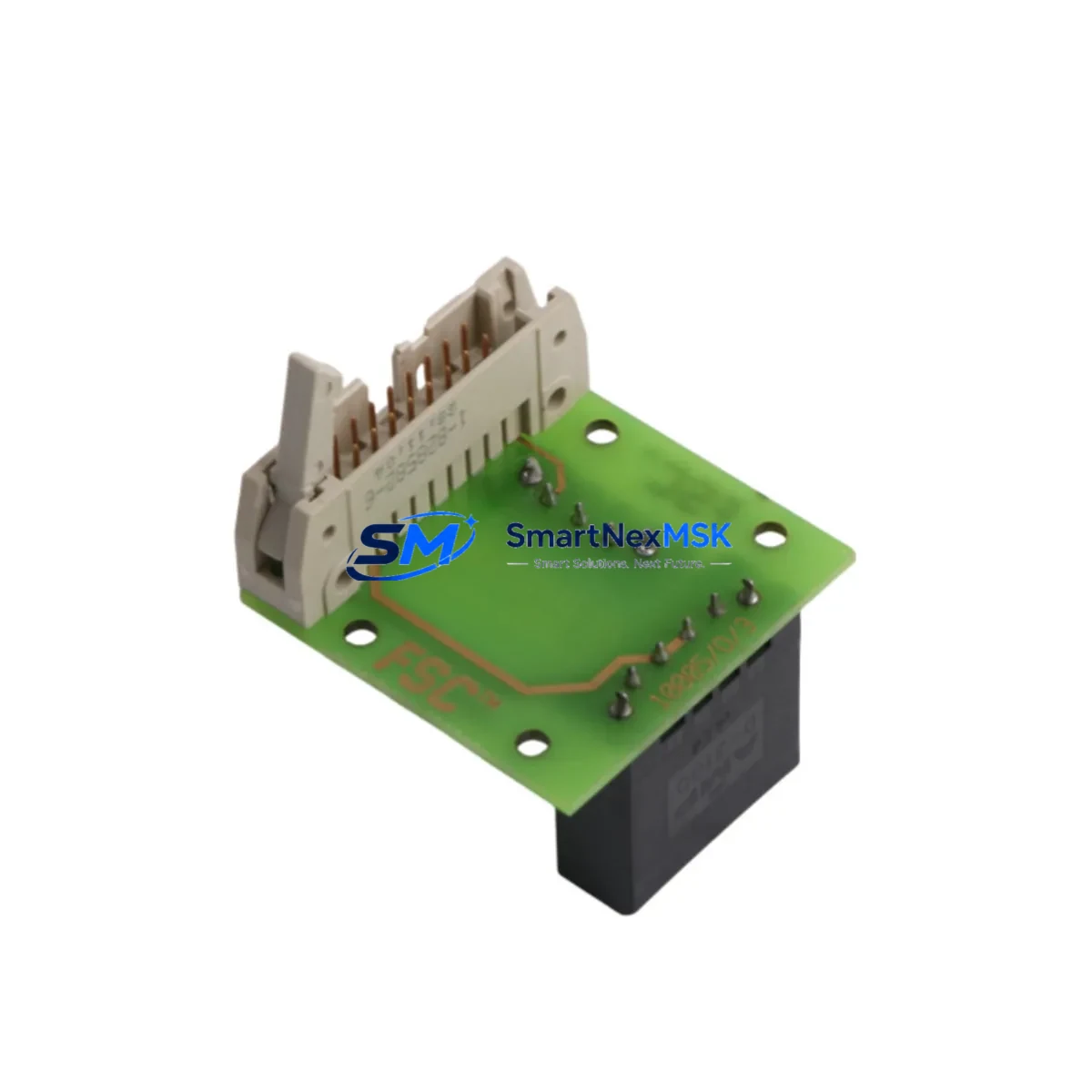
The Honeywell 10005/0/3 is a DCS communication module originally designed for the TDC 3000 distributed control system platform. As legacy TDC 3000 installations reach end-of-life and spare parts become increasingly scarce, the 10005/0/3 remains one of the most sought-after replacement and retrofit components for engineers managing aging process control infrastructure. Whether you are executing a like-for-like spare replacement, a partial system upgrade, or a full control architecture migration, this module provides the compatibility baseline required to maintain operational continuity with minimal disruption to existing field wiring, backplane connections, and control logic.
Our inventory of the Honeywell 10005/0/3 is sourced, inspected, and dispatch-tested to ensure functional equivalence with the original factory specification. Each unit undergoes pre-shipment verification covering communication link integrity, backplane interface continuity, and module addressing. A 12-month warranty is included with every shipment.
Upgrade Compatibility Table
| Parameter | Details |
|---|---|
| Compatible Platform | Honeywell TDC 3000 DCS |
| Module Function | DCS Communication Module |
| Backplane Interface | TDC 3000 standard backplane slot — direct plug-in replacement |
| Installation Requirement | Standard DIN-rail or rack-mount enclosure; no mechanical modification required |
| Communication Compatibility | Compatible with LCN (Local Control Network) and UCN (Universal Control Network) topologies used in TDC 3000 architectures |
| Replacement Recommendation | Direct replacement for failed or end-of-life 10005/0/3 units; verify firmware revision before commissioning |
| Commissioning Focus | Module address configuration, network node assignment, and communication link verification via Honeywell Engineering Console |
| Warranty | 12 months from date of shipment |
Retrofit Planning for Existing Automation Systems
Replacing the Honeywell 10005/0/3 within an active TDC 3000 installation requires careful pre-work to avoid unplanned downtime and control logic disruption. Before removing the failed module, engineers should document the existing module address settings, verify the backplane slot assignment, and confirm the network node configuration within the Honeywell Universal Station or Engineering Workstation. The TDC 3000 platform uses a structured node-based communication architecture, and any mismatch in module addressing will prevent the replacement unit from joining the LCN or UCN network correctly.
In practice, a complete retrofit plan for a TDC 3000 communication upgrade typically involves several interdependent components beyond the 10005/0/3 itself. The High-Performance Process Manager (HPPM) or Basic Process Manager (BPM) controller cards housed in the same cabinet must be confirmed as compatible with the replacement module’s firmware revision. The Data Hiway Gateway module, if present, should be checked for protocol compatibility, particularly when the site is migrating from older Hiway-based I/O to UCN-connected Field Control Processors (FCP). Power supply modules within the TDC 3000 cabinet — typically the Honeywell 621-series or equivalent redundant power units — must be verified to provide adequate current capacity for the replacement module, especially if the retrofit involves adding additional I/O capacity through Honeywell PM I/O Link modules or Series C I/O termination assemblies.
For sites that are simultaneously upgrading their HMI layer, the transition from legacy Honeywell Universal Stations to modern Experion PKS Operator Stations introduces additional compatibility considerations. Display builder configurations and group displays referencing TDC 3000 point tags must be validated against the new communication path established through the replacement 10005/0/3. Where Modbus RTU or HART field devices are connected through Honeywell Smart Transmitter Interface Modules (STIM) or Multifunction Controllers (MFC), the communication chain from field device through the I/O subsystem to the DCS communication module must be re-verified after module replacement. Programming cables and configuration tools such as the Honeywell Control Builder or legacy HPM Configuration Tool should be on-site during commissioning to allow real-time parameter adjustment and fault diagnosis.
Downtime Control During System Migration
Minimizing downtime during a TDC 3000 communication module replacement is achievable with structured preparation. The recommended approach is to pre-configure the replacement 10005/0/3 offline using a bench test setup or a spare backplane chassis before the scheduled maintenance window. This allows the module address, network node parameters, and communication link settings to be verified in a non-production environment, reducing the time the live system is offline to the physical swap and final network re-synchronization steps only.
During the cutover, the existing control program logic stored in the Process Manager or High-Performance Process Manager is not affected by the communication module replacement, provided the module address and network node assignment are correctly replicated. Regulatory control loops, cascade strategies, and interlock logic will resume automatically once the replacement module establishes its LCN or UCN communication link. For critical process areas where continuous control is required, a temporary manual control strategy should be agreed with the operations team before the maintenance window begins, covering the period between module removal and network re-synchronization.
Field I/O signals connected through Series C or PM I/O termination assemblies remain powered and in their last-state output condition during the module swap, provided the power supply and backplane remain energized. This protects field actuators and control valves from uncontrolled state changes during the replacement procedure. After the replacement 10005/0/3 is installed and the network link is confirmed, a systematic loop check of all associated I/O channels should be completed before returning the system to automatic control.
Retrofit Support FAQ
Q: Is the Honeywell 10005/0/3 a direct drop-in replacement for the original module?
A: Yes, the 10005/0/3 is designed as a direct backplane-compatible replacement for the same part number in TDC 3000 installations. The physical connector, slot dimensions, and communication interface are identical to the original. However, engineers should verify the firmware revision of the replacement unit against the existing system configuration, as firmware mismatches can affect network initialization behavior.
Q: What commissioning steps are required after installing the replacement module?
A: After physical installation, the module address must be confirmed using the DIP switch or jumper settings on the module face, matching the original configuration. The Honeywell Engineering Console or Universal Station should then be used to verify that the module appears on the LCN or UCN network with the correct node identity. A communication link test and I/O channel scan should be completed before returning the associated control loops to automatic mode.
Q: Can the 10005/0/3 be used in a mixed TDC 3000 and Experion PKS environment?
A: The 10005/0/3 operates within the TDC 3000 communication architecture. In hybrid environments where TDC 3000 cabinets are connected to an Experion PKS system via an Application Control Environment (ACE) node or Server, the module continues to function as part of the TDC 3000 subsystem. Compatibility with the Experion layer depends on the ACE configuration and the version of Experion PKS in use. Consult your Honeywell system integrator for site-specific validation.
Q: What does the 12-month warranty cover?
A: The 12-month warranty covers manufacturing defects and functional failures under normal operating conditions. Each unit is pre-shipment tested for communication link integrity, backplane interface continuity, and module addressing. Warranty claims are supported by our technical team with replacement dispatch within agreed lead times. The warranty period begins from the date of shipment confirmation.
© 2026 SMARTNEXMSK. All rights reserved.
Original Source: https://smartnexmsk.com
Contact: sales@smartnexmsk.com | +86 18259474341