Honeywell 10310/3/1 Spare for 10310 Series Automation: Spare Replacement & Industrial Downtime Risk Control
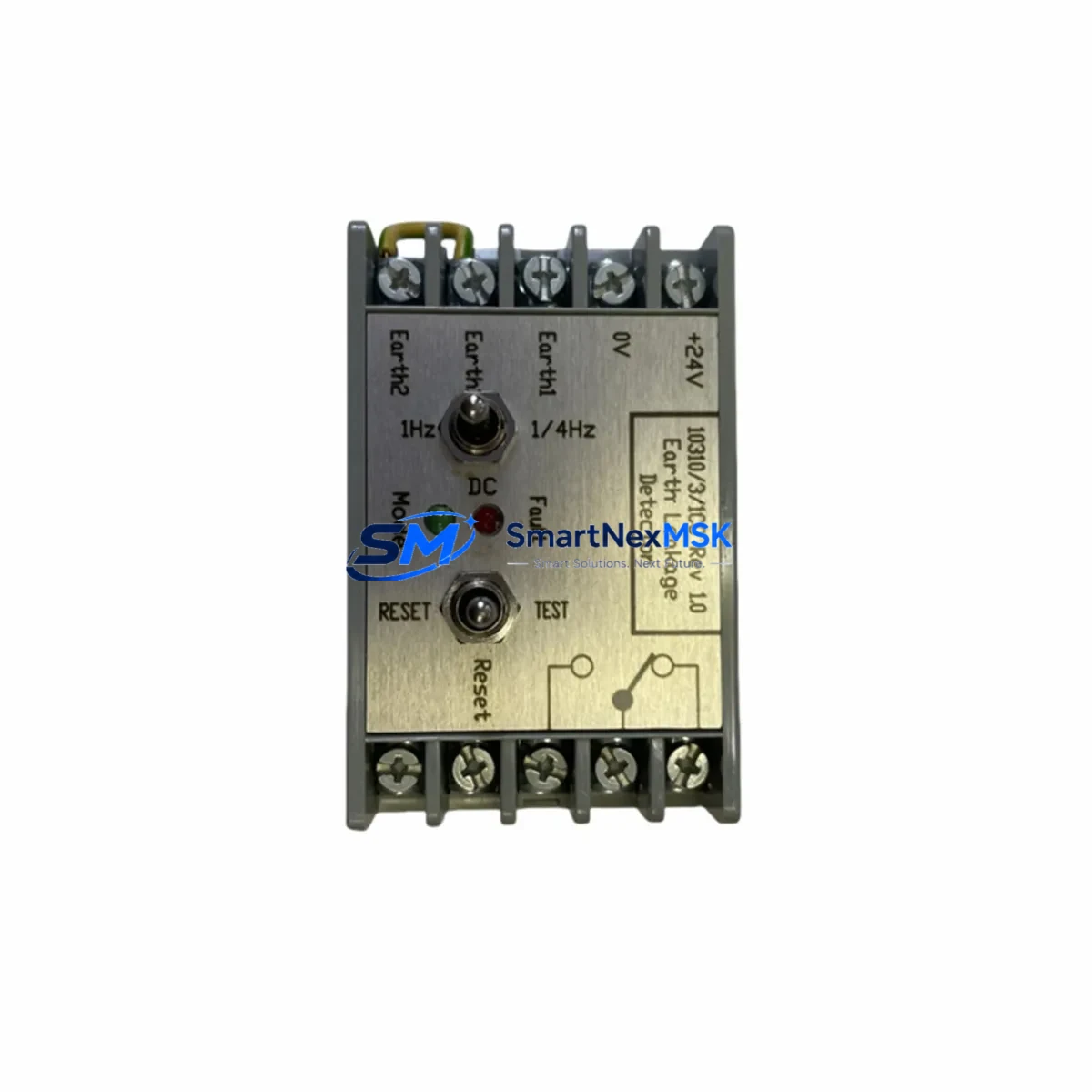
The Honeywell 10310/3/1 is a 3-phase earth leakage relay (ground fault relay) from the 10310 Series, designed for continuous protection of industrial power distribution systems, motor control centers, and automation control cabinets. As a maintenance-ready original spare, the 10310/3/1 is engineered to deliver direct drop-in replacement capability, minimizing unplanned downtime and supporting fast fault recovery in demanding industrial environments.
For maintenance engineers managing aging control systems, the 10310/3/1 represents a critical line of defense against insulation degradation, ground faults, and leakage current events that can trigger nuisance trips or — worse — undetected faults leading to equipment damage and personnel hazards. Stocking this relay as a verified spare ensures your team can execute a controlled replacement within a planned maintenance window rather than scrambling during an emergency shutdown.
Procurement engineers sourcing replacement parts for Honeywell 10310 Series panels will find the 10310/3/1 fully compatible with existing DIN rail mounting arrangements, terminal block wiring layouts, and relay socket configurations common to this series. No panel re-engineering is required — the unit installs directly into the existing footprint, restoring protection coverage and system integrity in the shortest possible time.
Spare Maintenance Table
| Parameter | Specification |
|---|---|
| SKU / Part Number | 10310/3/1 |
| Brand | Honeywell |
| Series | 10310 Series |
| Product Type | Earth Leakage Relay / Ground Fault Relay |
| Phase Configuration | 3-Phase |
| Mounting | DIN Rail |
| Application | Motor control centers, power distribution panels, industrial automation cabinets |
| Compatibility | Direct replacement for Honeywell 10310 Series installations |
| Installation Environment | Industrial control cabinets, MCC panels, switchgear enclosures |
| Maintenance Recommendation | Inspect annually; replace immediately upon trip failure or insulation degradation detection |
| Origin | United States (Honeywell OEM) |
| Weight | 1,170 g |
| Warranty | 12 Months — tested and verified before dispatch |
Maintenance Planning for Continuous Operation
When scheduling a replacement of the Honeywell 10310/3/1 earth leakage relay, a thorough maintenance engineer will treat the relay swap as an opportunity to inspect the entire protective circuit and associated components. Replacing only the relay while leaving degraded ancillary components in place is a common cause of repeat faults and premature relay failure.
Begin by verifying the upstream power supply module feeding the relay’s auxiliary control voltage. A fluctuating or out-of-tolerance supply voltage is a leading cause of relay misoperation and should be confirmed with a calibrated meter before the new unit is energized. Next, inspect the current transformer (CT) wiring and toroidal core for mechanical damage, moisture ingress, or loose terminations — a compromised CT will render even a new relay unreliable.
Check all terminal block connections in the relay circuit, including the trip output contacts wired to the upstream circuit breaker or contactor coil. Loose or oxidized terminals introduce resistance that can cause delayed or failed trip signals. If the panel uses a dedicated relay output module or intermediate relay to interface the 10310/3/1 trip signal with the PLC or DCS input card, inspect that relay for contact wear and coil integrity.
For panels integrated with a PLC or DCS system, confirm that the digital input (DI) card receiving the earth fault trip signal is functioning correctly. A failed DI channel can mask a genuine earth fault event, preventing the control system from logging the fault or initiating an automatic shutdown sequence. Similarly, if a signal isolator or galvanic isolator is installed between the relay output and the control system input, verify its output signal level and isolation resistance.
Communication modules connected to the same control cabinet — such as PROFIBUS DP adapters, Modbus RTU gateways, or DeviceNet nodes — should be visually inspected for indicator status and communication health during the maintenance window. A ground fault event can induce transient voltages that stress communication hardware, and a relay replacement visit is an efficient time to confirm all network nodes are responding correctly.
Finally, review the HMI alarm history for any latent earth fault warnings, nuisance trips, or insulation resistance trend data that may indicate broader wiring degradation beyond the relay itself. Proactive replacement of aging fuse holders, surge protection devices (SPDs), and terminal markers in the same cabinet zone will extend the service life of the newly installed 10310/3/1 and reduce the frequency of future maintenance interventions.
Site Replacement Workflow
Step 1 — Isolation & Lockout/Tagout: De-energize the panel section containing the 10310/3/1. Apply LOTO procedures per site safety policy. Confirm absence of voltage on all terminals using an approved voltage tester.
Step 2 — Documentation: Photograph the existing relay wiring, terminal assignments, and DIN rail position before removal. Record the trip threshold setting and any adjustable parameters on the outgoing unit.
Step 3 — Removal: Disconnect all wiring from the relay terminals in sequence. Release the DIN rail locking tab and remove the relay from the rail. Inspect the vacated mounting position for corrosion, debris, or damaged terminal blocks.
Step 4 — Installation: Clip the replacement Honeywell 10310/3/1 onto the DIN rail. Reconnect all wiring per the documented terminal assignments. Torque all terminals to the manufacturer’s specified value to ensure reliable contact.
Step 5 — Configuration: Set the trip threshold and time delay parameters on the new relay to match the outgoing unit’s settings. Verify CT polarity and wiring orientation before energization.
Step 6 — Commissioning Test: Re-energize the circuit under controlled conditions. Inject a test leakage current using a relay test set to verify correct trip operation at the set threshold. Confirm the trip signal is received correctly by the upstream breaker or contactor and by the PLC/DCS input.
Step 7 — Documentation & Handover: Update the maintenance log with the replacement date, new relay serial number, test results, and next scheduled inspection date. Return the outgoing relay for failure analysis if required.
This workflow is compatible with both planned maintenance shutdowns and emergency replacement scenarios, and is designed to minimize total downtime while ensuring full system compatibility and protection coverage is restored before the panel is returned to service.
Spare Parts Support FAQ
Q1: Is the Honeywell 10310/3/1 a direct replacement for all 10310 Series installations?
Yes. The 10310/3/1 is designed as a direct drop-in replacement within the Honeywell 10310 Series. It maintains the same DIN rail footprint, terminal layout, and electrical interface as the original factory-installed unit. No panel modifications or adapter hardware are required for standard installations. If your installation includes non-standard wiring modifications, review the original panel drawings before installation.
Q2: How is the unit tested before dispatch?
Every Honeywell 10310/3/1 unit shipped by SMARTNEXMSK undergoes functional verification prior to dispatch. Testing confirms relay trip operation, output contact continuity, and auxiliary supply acceptance within specification. Units that do not pass functional verification are not dispatched. A 12-month warranty covers all units against manufacturing defects and functional failure under normal operating conditions.
Q3: What is the recommended spare parts stocking strategy for the 10310/3/1?
For facilities operating multiple panels with 10310 Series earth leakage protection, we recommend maintaining a minimum of one 10310/3/1 relay per five installed units as a buffer stock. For critical processes where an earth fault trip would cause significant production loss, a 1:1 hot-spare ratio is advisable. Long-term availability of original Honeywell 10310 Series components is not guaranteed as the product line matures, making early procurement of buffer stock a prudent risk management strategy.
Q4: Can the 10310/3/1 be used to replace older or discontinued Honeywell earth leakage relay models?
In many cases, yes — subject to compatibility verification. The 10310/3/1 shares the core protection function and DIN rail form factor with several earlier Honeywell earth leakage relay variants. However, trip threshold ranges, CT ratios, and auxiliary voltage ratings must be confirmed against the original specification before substitution. Contact our technical team with your existing relay model number and panel drawings for a compatibility assessment before ordering.
© 2026 SMARTNEXMSK. All rights reserved.
Original Source: https://smartnexmsk.com
Contact: sales@smartnexmsk.com | +86 18259474341