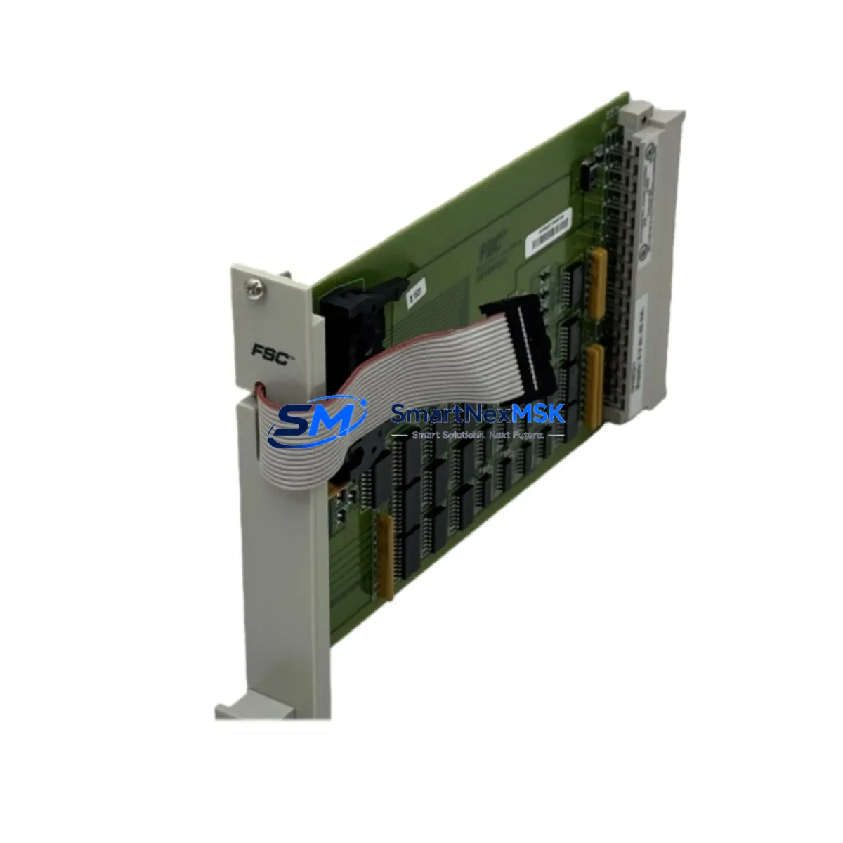
HONEYWELL 51403776-100 Spare for TDC 3000 Automation: Precision Spare Parts for DCS Downtime Recovery
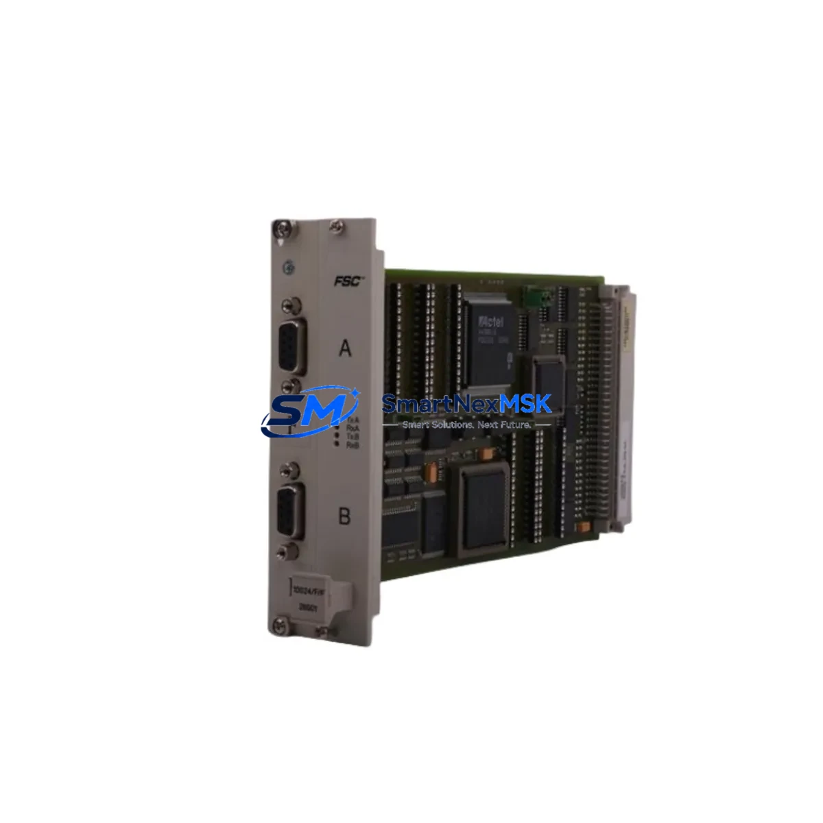
The HONEYWELL 51403776-100 is an original processor spacer board engineered for the TDC 3000 Distributed Control System platform — one of the most widely deployed DCS architectures in continuous-process industries including refining, petrochemical, power generation, and pulp & paper. When a card file slot fails or a spacer board degrades, the consequences extend beyond a single module: the entire card file assembly may lose structural integrity, increasing the risk of adjacent module faults, intermittent I/O errors, and unplanned process shutdowns.
Sourced directly from verified Honeywell supply channels, the 51403776-100 is inspected, function-tested, and shipped with a 12-month warranty. Each unit undergoes pre-shipment verification to confirm dimensional conformance, connector integrity, and compatibility with TDC 3000 card file assemblies. Whether you are executing a planned turnaround, responding to an emergency fault, or building a strategic spare parts inventory, this spacer board is a critical line item in any TDC 3000 maintenance BOM.
Spare Maintenance Table
| Parameter | Specification / Detail |
|---|---|
| Part Number | 51403776-100 |
| Manufacturer | Honeywell Process Solutions |
| Compatible Platform | TDC 3000 DCS (Local Control Network / High-Level Network) |
| Component Type | Processor Spacer Board / Card File Structural Component |
| Series | TDC 3000 / HPM / LCN Card File Assembly |
| Installation Environment | Control cabinet / card file enclosure, climate-controlled panel room |
| Operating Temperature | 0°C to 60°C (standard industrial panel environment) |
| Mounting | Card file slot insertion — tool-free, guided rail alignment |
| Compatibility | TDC 3000 card file assemblies; HPM, LCN, UCN node card files |
| Condition | Original / Refurbished-to-OEM-spec (inspected & tested) |
| Pre-Shipment Test | Dimensional check, connector pin inspection, functional verification |
| Weight | Approx. 1,980 g (packaged) |
| Origin | United States |
| Warranty | 12 Months — covers manufacturing defects and functional failure |
| Lead Time | In-stock: ships within 1–3 business days |
| Maintenance Recommendation | Inspect spacer boards during every scheduled card file PM; replace on first sign of mechanical deformation or connector wear |
Maintenance Planning for Continuous Operation
For maintenance engineers managing a TDC 3000 installation, the 51403776-100 spacer board is rarely a standalone replacement. Card file integrity depends on the coordinated condition of every component occupying the chassis. When scheduling a replacement of this spacer board — whether during a planned outage or an emergency response — experienced engineers use the opportunity to audit the full card file assembly and adjacent systems.
Begin with the card file power supply modules (such as the Honeywell 51401469-100 or equivalent HPM power supply). A degraded power rail is one of the leading causes of intermittent module faults that are often misdiagnosed as spacer or backplane issues. Verify output voltage stability under load before re-seating any processor or I/O module.
Next, inspect the High-Performance Manager (HPM) processor module and any co-resident I/O Link modules. The HPM communicates over the Universal Control Network (UCN), and a loose or corroded UCN coaxial tap or UCN cable assembly can introduce cyclic communication faults that mimic hardware failure. Check the 51304485-100 UCN tap and associated coax termination resistors while the card file is open.
For sites running Local Control Network (LCN) nodes, this is also the right moment to verify the condition of LCN interface cards and the 51401584-100 LCN cable connections at the node. LCN redundancy should be confirmed active on both paths before returning the card file to service.
On the I/O side, review the analog input/output modules (e.g., 51304754-150 AO module or 51309276-150 AI module) installed in adjacent slots. Vibration, thermal cycling, and age-related connector fatigue can cause marginal contact resistance that only manifests under process load. A spacer board replacement outage is the ideal window to reseat and inspect these modules without additional process risk.
Do not overlook the terminal assembly boards and field termination assemblies (FTAs) connected to the I/O modules. Corroded screw terminals, loose field wiring, and degraded surge protection components on the FTA are common sources of nuisance alarms and signal drift. Replacing the spacer board while leaving deteriorated FTA wiring in place is a missed opportunity that often results in a repeat call-out within weeks.
For sites with redundant HPM configurations, confirm that the standby HPM module (e.g., 51402573-150) is synchronized and ready for automatic switchover before taking the primary card file offline. Verify the redundancy status display on the Honeywell console or via the Station HMI before and after the replacement.
Finally, check the card file backplane connectors for oxidation or mechanical damage. A worn backplane is a systemic risk that a single spacer board replacement cannot resolve — if backplane connector wear is detected, escalate to a full card file assembly replacement and source the appropriate Honeywell card file chassis as part of your long-term spares strategy.
Site Replacement Workflow
Step 1 — Pre-Replacement Verification: Confirm the exact card file model and slot configuration using the TDC 3000 system documentation or the Honeywell Engineering Workstation (EWS). Verify that the replacement 51403776-100 part number matches the installed revision. Cross-reference the system’s hardware configuration database to confirm no firmware dependency exists on the spacer board revision.
Step 2 — Process Isolation: Coordinate with the control room operator to place affected loops in manual mode. For HPM-based card files, initiate a controlled HPM switchover to the redundant module if available. Document the current process state and alarm status before proceeding.
Step 3 — Card File De-energization: Follow site-specific LOTO (Lockout/Tagout) procedures. Remove power from the card file power supply. Allow capacitors to discharge per the Honeywell TDC 3000 hardware maintenance manual before touching any module or spacer board.
Step 4 — Removal and Inspection: Extract the faulty spacer board using the card file ejector levers. Inspect the vacated slot for debris, corrosion, or backplane connector damage. Clean the slot with approved electronics-safe compressed air or IPA wipes before inserting the replacement unit.
Step 5 — Installation and Seating: Insert the new 51403776-100 spacer board along the card file guide rails until the backplane connector is fully engaged. Confirm the ejector levers are locked. Do not force the board — misalignment will damage the backplane connector.
Step 6 — Power-Up and Verification: Restore card file power. Monitor the HPM status LEDs and the EWS hardware status display for fault indications. Confirm all I/O modules in the card file report healthy status. Return process loops to automatic control and verify signal integrity on all affected channels.
Step 7 — Documentation: Record the replacement in the site maintenance management system (CMMS). Log the removed part number, installation date of the new unit, and the 12-month warranty expiry date. Update the spare parts inventory to trigger reorder of a replacement unit for the spares cabinet.
Spare Parts Support FAQ
Q1: Is the 51403776-100 compatible with all TDC 3000 card file variants, including HPM and LCN node card files?
The 51403776-100 is designed for the TDC 3000 card file platform and is compatible with HPM, LCN, and UCN node card file assemblies that use the standard Honeywell card file chassis. Always verify the card file model number against your system hardware documentation before ordering. If you are unsure of compatibility, contact our technical team with your card file model and we will confirm fit before shipment.
Q2: What does the 12-month warranty cover, and what is the claims process?
The 12-month warranty covers manufacturing defects and functional failure under normal operating conditions. It does not cover damage resulting from incorrect installation, overvoltage events, or physical mishandling. To initiate a warranty claim, contact sales@smartnexmsk.com with the order number, fault description, and photographic evidence of the defect. Replacement or refund is processed within 5–7 business days of claim approval.
Q3: How should the 51403776-100 be stored as a long-term spare?
Store in the original anti-static packaging in a climate-controlled environment: temperature 15°C–35°C, relative humidity below 60%, away from direct sunlight and electromagnetic interference sources. Inspect the packaging seal annually. For long-term storage beyond 24 months, perform a visual inspection of connector pins and re-bag with fresh desiccant before returning to the spares cabinet.
Q4: Can this spacer board be used to extend the life of an aging TDC 3000 system scheduled for eventual migration?
Yes. The 51403776-100 is a proven component for TDC 3000 life extension programs. Many facilities operating legacy DCS platforms maintain a rolling spare strategy — keeping 2–3 spacer boards per card file type in stock — to sustain operations through planned migration windows without unplanned downtime. We support long-term supply agreements and can provide volume pricing for facilities building multi-year maintenance inventories.
© 2026 SMARTNEXMSK. All rights reserved.
Original Source: https://smartnexmsk.com
Contact: sales@smartnexmsk.com | +86 18259474341