Honeywell 620-0080 Maintenance-Ready Spare Series 620: Spare Replacement & Industrial Downtime Risk Control
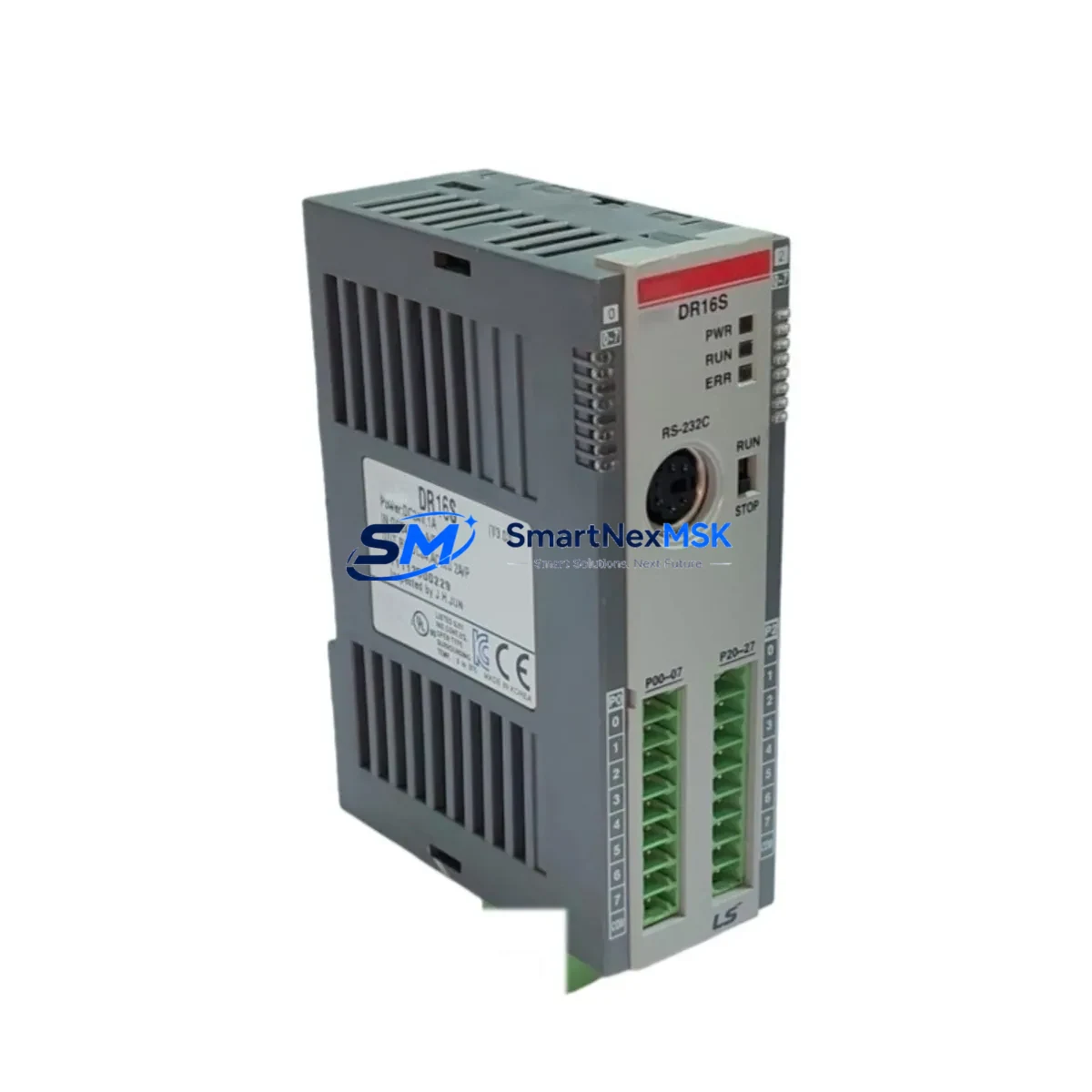
The Honeywell 620-0080 is a CPU module designed for the Series 620 Programmable Logic Controller platform — a proven architecture widely deployed across process manufacturing, utilities, and discrete automation facilities. When this module fails or degrades, the entire control loop it governs is at risk of unplanned shutdown. Sourcing a verified, maintenance-ready spare is the fastest path to restoring normal operation and protecting production continuity.
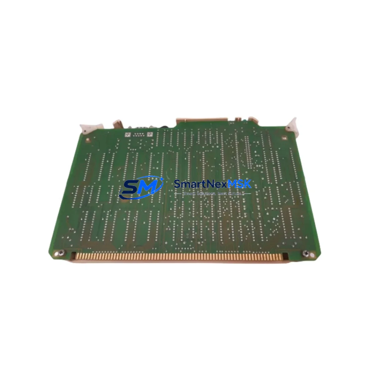
This listing provides an original Honeywell 620-0080 CPU module, sourced through established industrial supply channels, inspected prior to dispatch, and backed by a 12-month warranty. Whether you are responding to an active fault, executing a planned overhaul, or building a strategic spare parts inventory for aging Series 620 infrastructure, this unit is ready for immediate deployment.
Maintenance engineers working on Series 620 systems understand that the CPU module is the nerve center of the rack. Its failure typically manifests as loss of scan cycle, communication dropout to the programming terminal, or complete rack halt. Rapid identification and replacement of the 620-0080 — without waiting weeks for OEM lead times — is critical to minimizing mean time to repair (MTTR) and protecting SLA commitments.
Spare Maintenance Table
| Parameter | Specification / Detail |
|---|---|
| Part Number / SKU | 620-0080 |
| Brand | Honeywell |
| Series / Platform | Series 620 PLC |
| Module Type | CPU / Processor Module |
| Form Factor | Rack-mount, Series 620 backplane compatible |
| Power Supply Compatibility | Series 620 rack power supply (620-0036 / 620-0037 class) |
| Communication Interface | Series 620 proprietary backplane bus; programming port |
| Operating Temperature | 0°C to 60°C (standard industrial enclosure) |
| Mounting / Installation | Slide-in rack slot, backplane connector engagement |
| Application Environment | Process control, utilities, discrete manufacturing, legacy DCS migration |
| Compatibility | Direct replacement for Honeywell Series 620 CPU slot |
| Condition | Original / Refurbished — inspected and function-tested |
| Pre-shipment Testing | Power-on, communication, and scan-cycle verification |
| Warranty | 12 Months from date of shipment |
| Lead Time | In-stock — ships within 1–3 business days |
| Origin | USA (Honeywell Industrial Automation) |
Maintenance Planning for Continuous Operation
Replacing the 620-0080 CPU module is rarely an isolated task. Experienced maintenance engineers treat a CPU swap as an opportunity to audit the entire control cabinet and associated electrical circuit. Before returning the system to service, the following components should be inspected or replaced as part of a comprehensive maintenance event:
Power Supply Module (e.g., 620-0036 / 620-0037): The rack power supply is the first upstream component to verify. A marginal or aging power supply can cause intermittent CPU resets, corrupted memory, or false fault indications. Confirm output voltage rails are within specification under load before inserting the replacement CPU.
I/O Modules (Digital Input / Digital Output / Analog I/O): Series 620 I/O modules share the backplane with the CPU. A shorted or failed I/O card can stress the backplane bus and contribute to CPU faults. Inspect all installed I/O modules — particularly 620-series digital input and analog output cards — for blown fuses, damaged connectors, or error LEDs.
Backplane / Rack Assembly: The Series 620 rack backplane provides the data and power bus between the CPU and all I/O modules. Inspect connector pins for corrosion, bent contacts, or contamination. A damaged backplane can cause persistent communication errors even after a CPU replacement.
Communication Module / Programming Interface: If the system uses a dedicated communication module for Modbus, Data Highway, or serial programming access, verify its firmware version is compatible with the replacement 620-0080 CPU. Mismatched firmware can prevent successful program upload or cause runtime communication faults.
Terminal Blocks and Field Wiring: Loose or corroded terminal block connections on I/O wiring are a common root cause of intermittent faults that are incorrectly attributed to the CPU. Torque-check all terminal screws and inspect for insulation damage or moisture ingress, particularly in high-vibration or humid environments.
Relay Output Modules and Interposing Relays: Relay output modules in the Series 620 rack — and any interposing relays in the field wiring panel — should be tested for contact resistance and coil integrity. Welded or high-resistance relay contacts can cause field device faults that appear as CPU or I/O errors.
Signal Isolators and Analog Conditioning: For analog I/O loops, verify that signal isolators and loop-powered transmitters are functioning correctly. A failed isolator can inject noise or ground loops into the analog input cards, causing erratic process values and triggering CPU fault routines.
Fuses and Circuit Protection: Inspect all panel fuses — both on the power supply input and on individual I/O field circuits. Replace any fuses that show signs of thermal stress or that measure above rated resistance. Document fuse ratings against the original panel drawings to prevent future overcurrent events.
HMI / Operator Interface Terminal: If the Series 620 system communicates with an HMI or operator panel, verify that the communication cable, port settings, and HMI firmware are compatible with the replacement CPU. Some older HMI units require specific CPU firmware versions for stable Modbus or proprietary protocol communication.
Battery / Memory Backup: Many Series 620 CPU modules use an onboard lithium battery to retain program memory during power loss. When installing a replacement 620-0080, confirm the battery is present, charged, and within its service life. A dead battery will result in program loss on the next power cycle.
Site Replacement Workflow
Step 1 — Pre-Replacement Documentation: Before removing the existing 620-0080, upload or print the current PLC program from the programming terminal. Record all I/O module slot assignments, communication port settings, and any DIP switch or jumper configurations on the CPU. Photograph the rack layout and wiring for reference.
Step 2 — Safe Isolation: Follow site lockout/tagout (LOTO) procedures. De-energize the rack power supply and verify zero voltage at the backplane power rails before handling any modules. Do not hot-swap the CPU module unless the system documentation explicitly supports it.
Step 3 — Module Removal and Inspection: Slide out the faulty 620-0080 and inspect the backplane connector for damage. Clean the slot with dry compressed air if contamination is present. Inspect the removed module for visible damage — burnt components, cracked PCB, or corroded connectors — to help identify the root cause of failure.
Step 4 — Replacement Installation: Insert the replacement 620-0080 into the CPU slot, ensuring full backplane connector engagement. Secure the module retaining latch or screws per the Series 620 hardware manual. Restore power and observe the CPU status LEDs during the boot sequence.
Step 5 — Program Restore and Verification: Download the saved program to the replacement CPU via the programming terminal. Verify program checksum, I/O configuration, and communication settings. Place the system in RUN mode and confirm all I/O points are responding correctly before releasing the system to production.
Step 6 — Post-Replacement Documentation: Record the replacement date, new module serial number, and any configuration changes in the site maintenance log. Update the spare parts inventory to reflect the consumed unit and initiate a reorder to maintain minimum stock levels.
Spare Parts Support FAQ
Q1: Is the 620-0080 still available as a new original part, or is it end-of-life?
The Honeywell Series 620 platform has been discontinued by the OEM, meaning new factory stock is no longer produced. However, original units remain available through specialist industrial spare parts suppliers who maintain legacy inventory. All units we supply are inspected, function-tested, and backed by a 12-month warranty — providing a reliable alternative to costly system migration for facilities that need to extend the operational life of their Series 620 infrastructure.
Q2: How do I verify compatibility before installation?
Compatibility verification should include: (1) confirming the rack model accepts the 620-0080 in the CPU slot, (2) checking that the firmware version on the replacement unit is compatible with your existing I/O modules and communication configuration, and (3) verifying that your programming software version supports the replacement CPU. We recommend consulting the Series 620 hardware reference manual and, if needed, contacting our technical team with your rack model and software version for pre-purchase confirmation.
Q3: What testing is performed before shipment?
Every 620-0080 unit undergoes a pre-shipment inspection that includes visual examination for physical damage, power-on functional test, scan-cycle verification, and communication port check. Units that do not pass all test criteria are not dispatched. A test report is available upon request. The 12-month warranty covers defects in materials and workmanship under normal operating conditions.
Q4: What is the recommended spare parts stocking strategy for Series 620 systems?
For facilities operating multiple Series 620 racks, we recommend maintaining at minimum one spare 620-0080 CPU module per site, plus one spare power supply module and one spare of each I/O module type in active use. Given the end-of-life status of the platform, procurement lead times for legacy spares can be unpredictable. Establishing a strategic buffer stock — particularly for CPU and power supply modules — significantly reduces the risk of extended downtime caused by parts unavailability. We offer long-term supply agreements and reserved inventory programs for high-volume MRO customers.
© 2026 SMARTNEXMSK. All rights reserved.
Original Source: https://smartnexmsk.com
Contact: sales@smartnexmsk.com | +86 18259474341