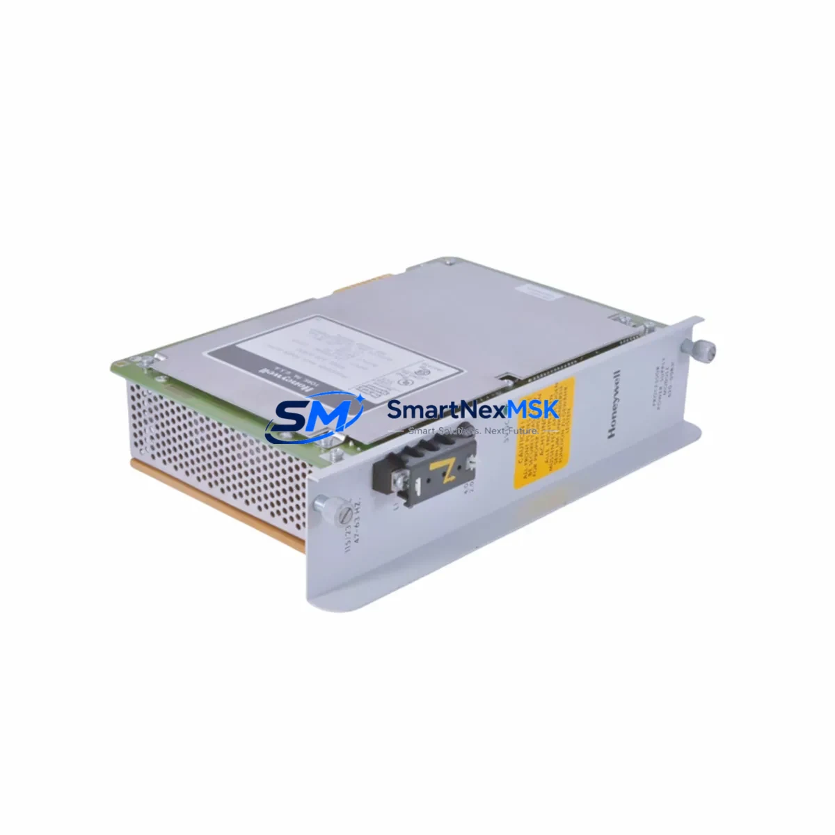
Honeywell 620-0083 Retrofit-Ready Power Supply for Series 620 Control Systems
The Honeywell 620-0083 is a proven power supply module engineered for the Series 620 Programmable Logic Controller platform — one of Honeywell’s most widely deployed process automation architectures in petrochemical, power generation, and discrete manufacturing environments. As the Series 620 platform approaches end-of-life and spare parts become increasingly scarce, the 620-0083 remains a critical retrofit component for engineers tasked with extending the operational life of existing control cabinets without committing to a full DCS migration.
This module delivers regulated DC power to the Series 620 backplane, supporting both local I/O racks and remote I/O expansion chassis. When replacing a failed or degraded unit, engineers must verify the input voltage range (typically 115/230 VAC selectable), output current capacity, and connector pinout against the existing rack wiring harness. The 620-0083 is designed for direct substitution in standard Series 620 rack assemblies, but field technicians should confirm the rack slot assignment and any address jumper settings before powering up the replacement unit.
Sourced from verified surplus and refurbished channels, each 620-0083 unit shipped by SMARTNEXMSK undergoes functional load testing, visual inspection, and output voltage verification prior to dispatch. All units carry a 12-month warranty covering manufacturing defects and functional failure under normal operating conditions.
Upgrade Compatibility Table
| Parameter | Details |
|---|---|
| SKU / Part Number | 620-0083 |
| Brand / Manufacturer | Honeywell |
| Compatible Platform | Honeywell Series 620 PLC |
| Module Function | Power Supply Module |
| Input Voltage | 115 VAC / 230 VAC (field selectable) |
| Rack / Backplane Interface | Series 620 standard backplane connector |
| Installation Requirement | Slot 0 (power supply bay); verify rack model before installation |
| Communication Compatibility | Passive power supply; no protocol dependency |
| Replacement Recommendation | Direct drop-in for failed or degraded 620-0083 units in Series 620 racks |
| Commissioning Notes | Verify output voltage under load; confirm jumper settings match site wiring |
| Warranty | 12-Month Warranty (functional failure and manufacturing defects) |
| Origin | USA (Honeywell manufactured); tested and dispatched from SMARTNEXMSK stock |
Retrofit Planning for Existing Automation Systems
A successful Series 620 retrofit begins well before the replacement module arrives on site. Engineers should pull the existing rack wiring diagram and confirm the power supply bay dimensions, terminal block layout, and any field-wired AC input connections. In many installations, the 620-0083 shares a control cabinet with the Series 620 CPU module (such as the 620-0016 or 620-0017 processor cards), multiple 620-series digital input and digital output modules, and analog I/O cards handling 4–20 mA process signals from field instruments.
Where the control system also includes a 620-series communication module — for example, a Data Highway or Modbus RTU interface card — the power budget of the replacement supply must be validated against the total rack load. Adding a new communication module or expanding I/O capacity as part of the same retrofit project can push the rack’s power demand beyond the original design margin, making it essential to calculate the aggregate current draw of all installed modules before commissioning the 620-0083.
For sites running a hybrid architecture where the Series 620 PLC feeds process data to a Honeywell TDC 3000 or Experion PKS supervisory layer, the power supply replacement must be coordinated with the DCS historian and alarm management team to avoid spurious process alarms during the switchover window. Similarly, if the rack communicates with a remote I/O chassis via a 620-series I/O link module, the link must be re-established and verified after the power supply is seated and energized.
Panel builders and system integrators handling control cabinet upgrades should also account for the 620-series rack chassis itself — older backplanes may show connector wear or corrosion that can cause intermittent power faults even after a new supply is installed. In such cases, a concurrent backplane inspection or chassis replacement using a compatible Series 620 rack assembly is advisable. Programming cables used to connect a laptop to the Series 620 CPU for program backup and verification (typically a dedicated serial programming cable compatible with Honeywell’s Series 620 programming software) should be prepared in advance so that the existing ladder logic or function block program can be uploaded, verified, and reloaded without delay.
Downtime Control During System Migration
Minimizing unplanned downtime during a Series 620 power supply replacement requires a structured pre-outage checklist. Before de-energizing the rack, the site engineer should perform a full program backup from the 620 CPU to a laptop using the Series 620 programming software, document all I/O module addresses and channel assignments, and photograph or sketch the existing terminal wiring on the power supply input terminals. Where the process permits, a controlled shutdown sequence should be initiated through the HMI — whether a legacy Honeywell operator station or a modern Experion PKS console — to bring all outputs to a safe state before power is removed.
During the physical swap, the replacement 620-0083 should be inserted into the power supply bay with the rack de-energized. After seating the module and securing any retaining hardware, the AC input voltage selector should be confirmed against the site supply voltage before re-energizing. On power-up, the engineer should monitor the backplane bus voltage using a calibrated multimeter at the rack’s test points before allowing the CPU module to resume scan. If the CPU does not restart automatically, a manual program reload from the backup file may be required.
For critical continuous-process applications where even a brief control interruption is unacceptable, a hot-standby or redundant power supply configuration using a second 620-0083 in a redundant rack assembly can eliminate single-point-of-failure risk. SMARTNEXMSK maintains buffer stock of the 620-0083 specifically to support emergency dispatch scenarios, with same-day shipping available for in-stock units to minimize the gap between fault detection and system restoration.
Retrofit Support FAQ
Q1: Is the 620-0083 a direct replacement for all Series 620 rack configurations?
The 620-0083 is designed for the standard Series 620 power supply bay and is compatible with the majority of Series 620 rack assemblies. However, some early-revision racks or custom OEM configurations may use a variant power supply with different connector pinouts or output ratings. Always cross-reference the existing module’s label and the rack wiring diagram before ordering. SMARTNEXMSK’s technical team can assist with cross-referencing if you provide the full rack model number and existing module label details.
Q2: What commissioning steps are required after installing the replacement unit?
After physical installation, verify the AC input voltage selector matches the site supply, confirm output DC bus voltage at the rack test points, and check that all I/O module status LEDs return to normal run state. Reload the CPU program from backup if the processor does not resume scan automatically. Re-establish any communication links (Data Highway, Modbus RTU, or I/O link) and verify HMI data integrity before returning the system to automatic control.
Q3: How is wiring compatibility confirmed for the terminal block connections?
The 620-0083 uses the standard Series 620 power supply terminal block layout. Field wiring for AC input (L1, L2/N, PE) connects to the module’s screw terminals. Before disconnecting the existing wiring, photograph or label each conductor and record the terminal assignment. The replacement module’s terminal block is mechanically identical, allowing direct reconnection without rewiring. If the existing wiring uses ferrules or ring terminals, inspect for corrosion or insulation damage and replace as needed before reconnecting.
Q4: What does the 12-month warranty cover, and what is the return process?
All 620-0083 units supplied by SMARTNEXMSK carry a 12-month warranty from the date of shipment, covering functional failure and manufacturing defects under normal operating conditions. Warranty claims are initiated by contacting sales@smartnexmsk.com with the order reference, a description of the fault, and photographic evidence of the installation. SMARTNEXMSK will arrange return shipping and dispatch a replacement unit upon fault verification. Physical damage caused by incorrect installation, overvoltage, or environmental exposure is excluded from warranty coverage.
© 2026 SMARTNEXMSK. All rights reserved.
Original Source: https://smartnexmsk.com
Contact: sales@smartnexmsk.com | +86 18259474341