Honeywell 621-0024R Retrofit-Ready Pulse Input Module for Series 620 Control Systems
The Honeywell 621-0024R is a Pulse Input Module engineered for the Series 620 programmable controller platform — one of Honeywell’s most widely deployed legacy control architectures in process manufacturing, utilities, and discrete automation. As the Series 620 platform approaches end-of-life support, facilities managers and control engineers are increasingly sourcing the 621-0024R as a direct retrofit replacement to extend operational life, avoid costly full-system migrations, and maintain production continuity without unplanned downtime.
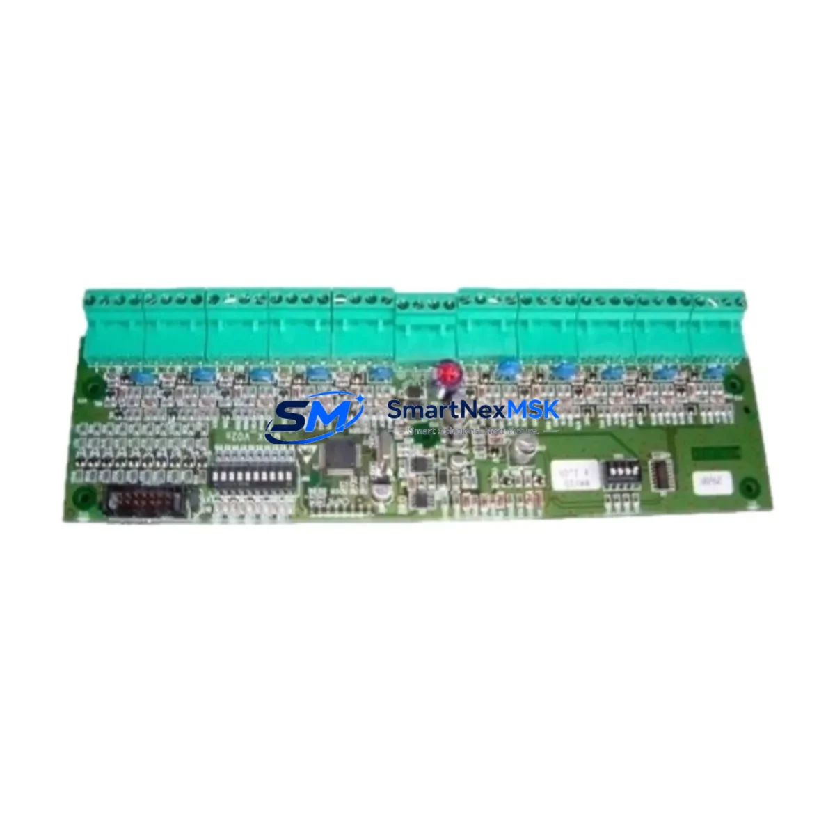
This module accepts high-frequency pulse signals from flow meters, encoders, turbine meters, and proximity sensors, converting them into digital count or rate values readable by the Series 620 CPU. Its compatibility with the standard Series 620 backplane and rack architecture means no chassis modification is required during installation — a critical advantage when working within confined control cabinet footprints or when minimizing retrofit scope.
Upgrade Compatibility Table
| Parameter | Detail |
|---|---|
| Module SKU | 621-0024R |
| Platform Compatibility | Honeywell Series 620 PLC |
| Module Type | Pulse Input Module |
| Backplane Interface | Series 620 standard backplane slot |
| Installation Requirement | Direct slot replacement; no chassis modification |
| Signal Input Type | High-frequency pulse (flow meters, encoders, proximity sensors) |
| Communication Compatibility | Series 620 internal bus protocol |
| Replacement Recommendation | Drop-in replacement for original 621-0024R; verify terminal wiring map before swap |
| Commissioning Notes | Confirm module address DIP switch settings match original; validate pulse scaling in CPU program |
| Warranty | 12-Month Warranty — covers manufacturing defects and functional failure under normal operating conditions |
Retrofit Planning for Existing Automation Systems
A successful 621-0024R retrofit begins well before the module arrives on-site. Engineers should pull the existing rack layout drawing and confirm the slot assignment of the original Pulse Input Module within the Series 620 chassis. The Series 620 rack — typically a 621-0001 or 621-0002 chassis — accommodates a fixed number of I/O slots, and the module address is determined by physical slot position combined with DIP switch configuration on the module face.
Before powering down, document the terminal block wiring on the existing module. The 621-0024R uses a removable terminal strip, which simplifies field replacement significantly — the wiring harness can be transferred directly to the new module without re-terminating individual conductors. Verify that the pulse signal source (e.g., a turbine flow meter or magnetic pickup encoder) operates within the input voltage and frequency range specified for the 621-0024R to avoid signal integrity issues post-swap.
On the software side, the Series 620 CPU — such as the 620-0016 or 620-0035 processor module — stores the I/O configuration and ladder logic program in battery-backed RAM. Before the retrofit, upload and archive the current program using a Series 620-compatible programming terminal or cable. Confirm that the pulse input channel addresses referenced in the program match the physical slot and channel assignments of the replacement module. If the original module had accumulated count registers, note the current values so they can be preset in the CPU after module swap to avoid process upsets.
For facilities running Series 620 alongside a Honeywell TDC 3000 or PlantScape supervisory system, verify that the data highway or peer-to-peer communication link remains unaffected during the module swap. The 621-0024R does not directly participate in the data highway — communication is handled by the Series 620 CPU and its associated 621-9937 or similar communication module — but a brief CPU restart during commissioning may temporarily interrupt data highway traffic. Coordinate with the DCS operator before initiating the swap.
If the retrofit is part of a broader I/O expansion or control cabinet upgrade, consider auditing adjacent modules in the same rack: analog input modules such as the 621-0020 or 621-0022, digital output modules, and the rack power supply unit (PSU) should all be inspected for age-related degradation. A failing PSU is a common root cause of intermittent module faults in aging Series 620 installations, and replacing it proactively during a planned retrofit window avoids a secondary unplanned outage.
Downtime Control During System Migration
Minimizing downtime during a 621-0024R swap requires a structured pre-outage checklist. Begin by scheduling the replacement during a planned maintenance window — ideally aligned with a shift change or scheduled process hold — to limit production impact. Prepare the replacement module in advance: verify the DIP switch address settings match the original, confirm the module powers up correctly on a bench test rack if available, and have the terminal wiring diagram ready for the field technician.
During the outage, follow a strict sequence: isolate the field signal inputs at the junction box before removing the original module, transfer the terminal strip to the replacement 621-0024R, insert the module into the correct rack slot, and restore field signal connections. Power up the rack and observe the module status LED — a solid green indication confirms successful initialization and backplane communication with the Series 620 CPU.
After power-up, force a program scan and verify that the pulse input channel is reading correctly in the CPU data table. Compare live pulse counts against a known reference (e.g., a portable flow meter or encoder tester) to confirm signal integrity. If the HMI — whether a legacy Honeywell Series 1 operator panel or a modern SCADA workstation connected via OPC — displays the correct process value, the retrofit is complete. Total swap time for an experienced technician is typically 30 to 90 minutes, keeping unplanned downtime risk to a minimum.
For sites where even brief interruptions are unacceptable, consider a hot-standby approach using a redundant Series 620 rack if the system architecture supports it. In non-redundant installations, pre-staging the replacement module and having a second technician monitor the HMI during the swap can further compress the outage window.
Retrofit Support FAQ
Q: Is the 621-0024R a direct drop-in replacement for the original module?
A: Yes. The 621-0024R is designed for direct slot replacement within the Series 620 rack. The removable terminal strip allows the existing field wiring to be transferred without re-termination. Confirm DIP switch address settings match the original module before installation.
Q: What commissioning steps are required after installing the replacement module?
A: After physical installation, power up the rack and verify the module status LED. In the Series 620 CPU program, confirm that the pulse input channel address is correctly mapped and that pulse scaling parameters (counts per unit, rate calculation) are intact. Validate live readings against a known reference signal before returning the system to automatic control.
Q: How do I verify wiring compatibility between the old and new module?
A: Reference the original Series 620 I/O wiring diagram for the 621-0024R terminal assignments. The terminal strip is removable and pin-compatible between original and replacement units. Check field signal voltage levels and pulse frequency against the module’s input specifications to confirm compatibility before energizing.
Q: What does the 12-month warranty cover?
A: The 12-month warranty covers manufacturing defects and functional failure under normal operating conditions from the date of shipment. Each unit undergoes pre-shipment functional testing to verify pulse input reception, backplane communication, and status indication. Warranty claims are supported by our technical team at sales@smartnexmsk.com.
© 2026 SMARTNEXMSK. All rights reserved.
Original Source: https://smartnexmsk.com
Contact: sales@smartnexmsk.com | +86 18259474341