Honeywell C7027A1064 Maintenance-Ready Spare C7027 Series: Spare Replacement & Industrial Downtime Risk Control
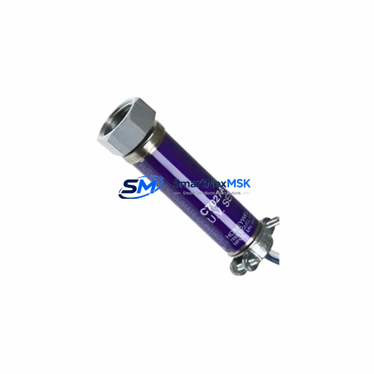
The Honeywell C7027A1064 and C7027A1072 are original UV flame sensors designed for industrial burner management systems operating within the C7027 Series platform. These sensors serve as critical detection components in combustion control loops, providing reliable ultraviolet flame signal feedback to flame safeguard controls such as the Honeywell R7847 or R7849 amplifier modules. For maintenance engineers managing boiler rooms, process heaters, or industrial furnaces, keeping a verified spare of the C7027A1064 on the shelf is a fundamental element of any proactive maintenance strategy.
Unplanned burner shutdowns caused by a failed UV flame sensor can halt production lines, disrupt thermal processes, and trigger costly emergency service calls. The C7027A1064 and its interchangeable variant C7027A1072 are direct-fit replacements that restore system operation without requiring reconfiguration of the flame safeguard relay or burner controller. Their compact sighting tube design allows installation in tight combustion chamber access points, and the UV-sensitive detection element is factory-calibrated to respond accurately to the specific spectral range of natural gas, oil, and dual-fuel burner flames.
From a procurement standpoint, sourcing original Honeywell C7027 Series sensors through a verified industrial spare parts supplier ensures traceability, consistent quality, and access to technical documentation. Each unit shipped by SMARTNEXMSK undergoes pre-shipment functional verification and is backed by a 12-month warranty covering manufacturing defects and detection performance.
Spare Maintenance Table
| Parameter | Specification |
|---|---|
| Part Numbers | C7027A1064 / C7027A1072 |
| Series | Honeywell C7027 |
| Sensor Type | UV (Ultraviolet) Flame Detector |
| Detection Spectrum | Ultraviolet (185–260 nm) |
| Supply Voltage | 120 VAC / 60 Hz (C7027A1064); 240 VAC / 50 Hz (C7027A1072) |
| Compatible Amplifiers | Honeywell R7847, R7849, R7851 Series |
| Compatible Controllers | Honeywell RM7800 Series, EC7800 Series Burner Controls |
| Mounting | 1-inch NPT sighting tube thread |
| Operating Temperature | -40°C to +60°C ambient |
| Application | Industrial boilers, process heaters, furnaces, dual-fuel burners |
| Origin | United States (Honeywell OEM) |
| Condition | New, Original OEM |
| Pre-Shipment Test | Functional UV response verification |
| Warranty | 12 Months |
| Lead Time | In stock — ships within 1–3 business days |
Maintenance Planning for Continuous Operation
When replacing the C7027A1064 UV flame sensor during a scheduled or emergency maintenance event, a thorough inspection of the surrounding combustion control circuit is strongly recommended. Maintenance engineers should treat a flame sensor replacement as an opportunity to audit the entire flame safeguard loop rather than a single-component swap.
Begin by inspecting the R7847 or R7849 amplifier module that processes the UV signal from the C7027A1064. Amplifier modules in continuous-duty burner applications accumulate operational hours rapidly, and a degraded amplifier can cause nuisance shutdowns even after a new sensor is installed. Similarly, the RM7800L or RM7800M burner control relay should be checked for contact wear, error history, and lockout frequency — these units are the central logic controllers that interpret the flame signal and command the fuel valve sequence.
The Q179 or Q624 sighting tube assembly should be cleaned and inspected for soot accumulation or lens fouling, which can attenuate the UV signal reaching the sensor. A contaminated sighting tube is one of the most common causes of intermittent flame failure codes in otherwise healthy systems. While the cabinet is open, inspect the S45 or S89 ignition transformer for output voltage integrity — a weak ignition spark can cause delayed flame establishment, placing unnecessary stress on the flame sensor’s detection cycle.
On the wiring side, verify the integrity of the flame sensor cable and connector between the C7027A1064 and the amplifier. UV sensor signal cables are low-voltage and susceptible to insulation degradation in high-temperature environments near the combustion chamber. Check terminal blocks and verify that the 24 VAC or 120 VAC control circuit supplying the burner control panel is within tolerance using a calibrated multimeter.
For facilities running multiple burner units, it is advisable to maintain at least one C7027A1064 and one C7027A1072 in the site spare parts inventory simultaneously, as the two variants cover different supply voltage configurations and are not always interchangeable without verifying the amplifier input specification. Pairing these with a spare R7847 amplifier and a set of RM7800 Series lockout reset modules creates a comprehensive first-response kit that covers the majority of burner flame failure scenarios without waiting for parts delivery.
Site Replacement Workflow
Step 1 — Isolate and de-energize: Follow site lockout/tagout (LOTO) procedures. Shut down the burner, close the manual fuel shutoff valve, and de-energize the burner control panel. Allow the combustion chamber to cool to a safe working temperature before accessing the flame sensor sighting tube.
Step 2 — Remove the failed sensor: Disconnect the sensor cable from the amplifier terminal. Unthread the C7027A1064 from the 1-inch NPT sighting tube fitting. Inspect the sighting tube interior for soot, scale, or moisture ingress. Clean with a dry lint-free cloth or compressed air before installing the replacement unit.
Step 3 — Install the replacement C7027A1064: Thread the new sensor into the sighting tube fitting and tighten to the manufacturer’s specified torque. Reconnect the sensor cable to the R7847 or R7849 amplifier, ensuring correct polarity and secure terminal contact. Verify that the cable routing does not place the cable in contact with hot surfaces.
Step 4 — Restore power and perform a flame signal check: Re-energize the control panel and initiate a burner start sequence. Monitor the flame signal strength reading on the amplifier or burner controller display. A healthy C7027A1064 should produce a stable UV signal reading within the amplifier’s acceptable range (typically above 1.0 VDC on R7847 systems). If the signal is marginal, recheck sighting tube alignment and cleanliness.
Step 5 — Document and update maintenance records: Record the replacement date, part number, and flame signal reading in the equipment maintenance log. Update the site spare parts inventory to trigger reorder of the consumed C7027A1064 unit, maintaining minimum stock levels for uninterrupted future maintenance response.
This workflow minimizes burner downtime to under two hours in most field scenarios and ensures the replacement is performed to OEM standards, preserving system compatibility with the existing RM7800 Series burner control infrastructure.
Spare Parts Support FAQ
Q1: Is the C7027A1064 a direct replacement for the C7027A1072?
The C7027A1064 (120 VAC / 60 Hz) and C7027A1072 (240 VAC / 50 Hz) are functionally equivalent UV flame sensors but differ in supply voltage rating. Before substituting one for the other, verify the supply voltage of your amplifier and burner control circuit. In most North American installations, the C7027A1064 is the correct variant; European and Asian 50 Hz systems typically require the C7027A1072. SMARTNEXMSK stocks both variants and can advise on compatibility based on your system documentation.
Q2: How do I verify the C7027A1064 is functioning correctly after installation?
After installation, initiate a supervised burner start and observe the flame signal reading on the connected R7847 or R7849 amplifier. A signal reading consistently above the amplifier’s minimum threshold (refer to the amplifier datasheet for exact values) confirms the sensor is detecting the UV flame signal correctly. If the reading is unstable or below threshold, inspect the sighting tube for fouling and verify cable integrity before concluding the sensor is defective.
Q3: What is the recommended spare parts inventory strategy for C7027 Series sensors?
For facilities with two or more burner units using C7027 Series sensors, maintaining a minimum of two spare sensors (one C7027A1064 and one C7027A1072 if both voltage variants are in use) is recommended. Flame sensors in continuous-duty applications should be considered for proactive replacement every 3–5 years as part of a planned maintenance interval, regardless of apparent condition, to prevent unplanned shutdowns during peak production periods.
Q4: What pre-shipment testing does SMARTNEXMSK perform on the C7027A1064?
Each C7027A1064 unit shipped by SMARTNEXMSK undergoes a functional UV response verification test prior to dispatch. Units are inspected for physical integrity, connector condition, and detection element functionality. All units are shipped in original or equivalent protective packaging with a 12-month warranty covering manufacturing defects and detection performance. Expedited shipping options are available for emergency maintenance situations requiring same-day or next-day dispatch.
© 2026 SMARTNEXMSK. All rights reserved.
Original Source: https://smartnexmsk.com
Contact: sales@smartnexmsk.com | +86 18259474341