Honeywell SZL-WLA-A-LL3 Retrofit-Ready Limit Switch for SZL Series Control Systems
The Honeywell SZL-WLA-A-LL3 is a precision snap-action limit switch engineered for seamless integration into legacy and modern industrial control systems. As a direct retrofit replacement within the MICRO SWITCH SZL Series, this unit addresses the growing demand for reliable, drop-in compatible components in aging automation infrastructure — particularly in applications where the original SZL-WLA-A-LL3 has been discontinued or is approaching end-of-life supply constraints.
Industrial facilities operating legacy PLCs, relay logic panels, and electromechanical control cabinets frequently encounter the challenge of sourcing exact-match limit switches without triggering full system redesigns. The SZL-WLA-A-LL3 resolves this by maintaining dimensional compatibility, terminal wiring layout, and actuation force characteristics consistent with the original SZL Series specification. Whether you are upgrading a conveyor control loop, a press safety interlock, or a door-position feedback circuit, this switch integrates without requiring panel rewiring or PLC program modification.
Before installation, engineers should verify the following parameters against the existing system: supply voltage and contact rating (AC/DC), terminal block pitch and wire gauge compatibility, actuator lever type and travel angle, mounting hole pattern on the control cabinet or machine frame, and the logic state (NO/NC) assigned in the PLC I/O table. In systems using a Honeywell SZL-WL-A or SZL-WLA-A base body, the LL3 lever head is a field-replaceable component, simplifying partial upgrades without full switch replacement.
Upgrade Compatibility Table
| Parameter | SZL-WLA-A-LL3 (This Unit) | Retrofit Notes |
|---|---|---|
| Series | Honeywell MICRO SWITCH SZL | Direct replacement within SZL Series family |
| Switch Type | Snap-Action Limit Switch | Compatible with relay, PLC digital input modules |
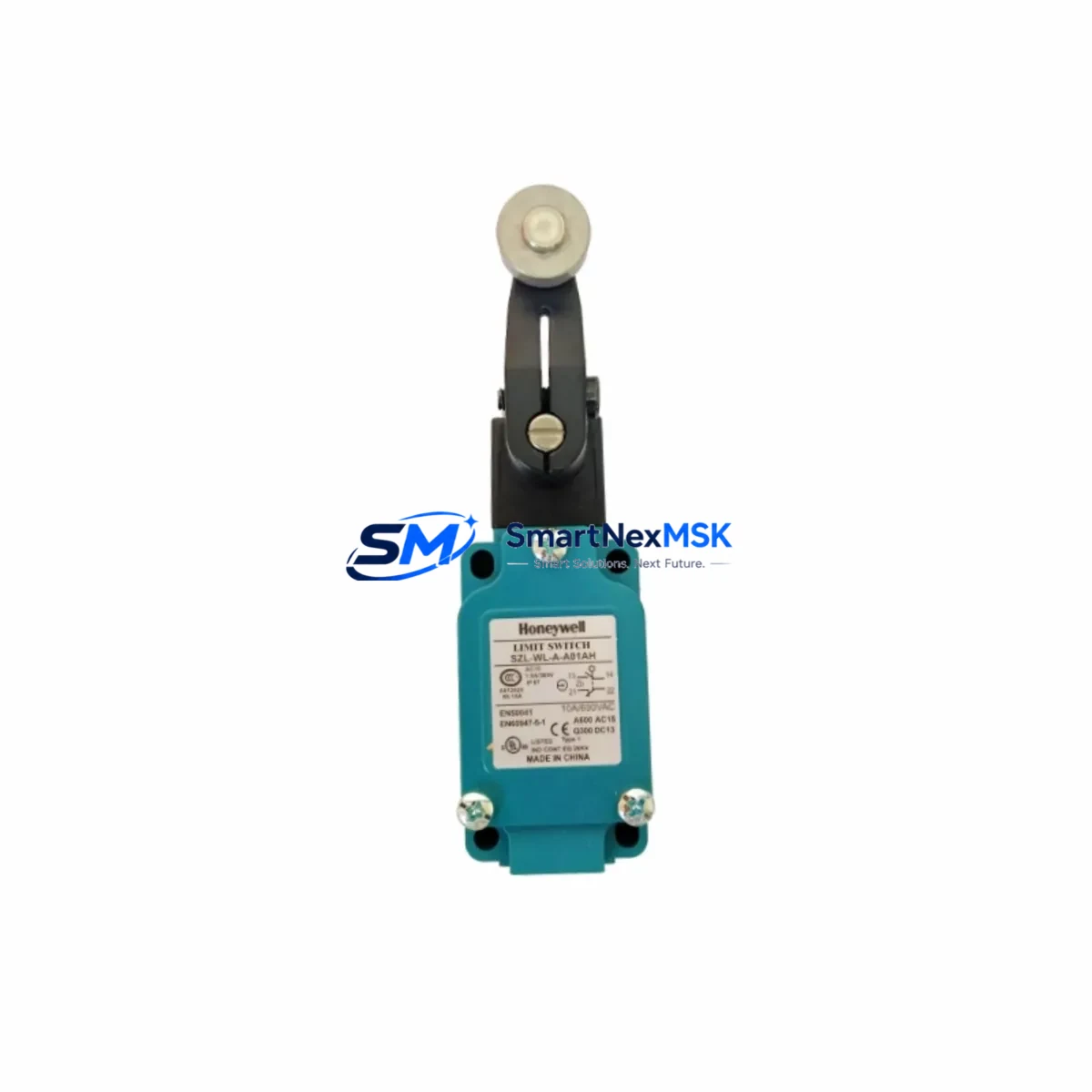
| Actuator | LL3 Roller Lever | Verify lever arm angle matches original travel path |
| Contact Configuration | SPDT (1NO + 1NC) | Confirm PLC I/O logic assignment before swap |
| Terminal Wiring | Screw terminal, standard pitch | Reuse existing wire ferrules; no re-crimping required |
| Mounting | Standard SZL body footprint | No panel drilling; bolt-in replacement |
| Communication Compatibility | Hardwired discrete signal | Compatible with all PLC digital input cards |
| Replacement Recommendation | 1:1 drop-in for SZL-WLA-A-LL3 | No program changes required in most applications |
| Commissioning Focus | Actuator alignment, contact continuity test | Use multimeter to verify NO/NC state before power-on |
| Warranty | 12 Months | Covers manufacturing defects; includes test certificate |
Retrofit Planning for Existing Automation Systems
Successful integration of the SZL-WLA-A-LL3 into an existing control system requires a structured approach to component mapping and pre-installation verification. In a typical retrofit scenario, the limit switch feeds a discrete input signal to a Honeywell HC900 Process Controller or a third-party PLC such as a Siemens S7-300 or Allen-Bradley MicroLogix 1400 via a 24VDC digital input module. The signal path typically runs through a terminal block assembly — commonly a Phoenix Contact PTFIX or Weidmüller WDU 2.5 rail-mount terminal — before reaching the controller’s I/O backplane.
When the SZL-WLA-A-LL3 is used as part of a broader control cabinet upgrade, it is common to simultaneously replace adjacent components such as the 24VDC power supply module (e.g., a Honeywell PS24VDC or equivalent DIN-rail PSU), the cable duct and wire management tray, and any aging relay output modules that interface with the switch signal downstream. In conveyor and press applications, the limit switch often works in tandem with a safety relay module — such as a Pilz PNOZ X or Schmersal SRB — to form a Category 3 safety circuit. Confirming that the SZL-WLA-A-LL3’s contact rating meets the safety relay’s input requirements is a mandatory pre-commissioning step.
For systems migrating from older electromechanical logic to PLC-based control, the SZL-WLA-A-LL3 can serve as a bridge component, providing a hardwired discrete feedback signal that is read by the new controller while legacy relay logic is phased out. In such migrations, engineers should document the original wiring diagram, photograph the existing terminal assignments, and create a cross-reference table mapping old terminal numbers to new PLC I/O addresses. This documentation supports both the commissioning phase and future maintenance cycles.
Where the control system includes an HMI panel — such as a Honeywell Experion PKS operator station or a standalone Weintek MT8000 touch panel — the limit switch status is typically displayed as a discrete indicator on the process mimic screen. After replacement, verify that the HMI tag linked to the corresponding PLC input address reflects the correct ON/OFF state during manual actuation testing. If the HMI shows an inverted state, check the NO/NC wiring assignment at the terminal block and adjust accordingly without modifying the PLC program logic.
Downtime Control During System Migration
Minimizing production downtime during a limit switch replacement is achievable with disciplined pre-staging and a clear isolation procedure. Before the maintenance window opens, pre-wire the replacement SZL-WLA-A-LL3 onto a spare terminal block strip and perform a bench-level continuity test to confirm correct NO/NC operation. Label all wires on the existing switch using adhesive ferrule markers before disconnection — this eliminates re-identification errors during reconnection under time pressure.
During the switchover, isolate the relevant PLC input channel by placing the associated rung in the ladder logic into a forced-ON or forced-OFF state (depending on the fail-safe requirement), ensuring that the control system does not generate a spurious fault or trigger an emergency stop sequence while the switch is physically disconnected. This technique preserves the original program logic intact and avoids the need for any program download or controller restart.
After physical installation, release the forced I/O state and perform a live actuation test: manually trigger the switch actuator and confirm that the PLC input indicator changes state in the controller’s online monitoring view. Cross-check the HMI display simultaneously. Total switchover time for a pre-staged SZL-WLA-A-LL3 replacement in a standard control cabinet is typically under 15 minutes, making it compatible with a planned short-stop maintenance interval rather than a full production shutdown.
All units shipped by SMARTNEXMSK are subject to pre-shipment functional testing, and each SZL-WLA-A-LL3 is accompanied by a test record confirming contact resistance, actuation force, and insulation integrity. The 12-month warranty covers manufacturing defects and provides a clear return path if any unit fails to perform within specification after installation.
Retrofit Support FAQ
Q1: Is the SZL-WLA-A-LL3 a direct replacement for the original Honeywell SZL-WLA-A-LL3 without any wiring changes?
A: Yes. The SZL-WLA-A-LL3 maintains the same body dimensions, terminal layout, and contact configuration as the original SZL Series specification. In the vast majority of retrofit applications, existing wiring can be reconnected directly to the replacement unit without modification. Always verify the actuator lever travel angle and mounting orientation before final installation.
Q2: What commissioning steps are required after installing the SZL-WLA-A-LL3 in a PLC-controlled system?
A: Perform a continuity test on the NO and NC contacts before energizing the circuit. After power-on, manually actuate the switch and confirm the corresponding PLC input channel changes state in the controller’s online diagnostic view. If an HMI is present, verify the process indicator reflects the correct switch state. Document the commissioning result and retain the pre-shipment test certificate for maintenance records.
Q3: Can the SZL-WLA-A-LL3 be used in safety-rated circuits?
A: The SZL-WLA-A-LL3 is a standard snap-action limit switch suitable for discrete control and position feedback applications. For use in functional safety circuits (e.g., Category 3 or PLd per ISO 13849), consult the full product datasheet and confirm compliance with the safety relay module’s input requirements. SMARTNEXMSK can provide datasheet documentation upon request.
Q4: What does the 12-month warranty cover, and how is a warranty claim processed?
A: The 12-month warranty covers manufacturing defects in materials and workmanship from the date of shipment. It does not cover damage resulting from incorrect installation, overvoltage, or mechanical abuse. To initiate a warranty claim, contact SMARTNEXMSK with the order reference number and a description of the fault. Replacement units are dispatched after fault verification, with return shipping coordinated by our technical support team.
© 2026 SMARTNEXMSK. All rights reserved.
Original Source: https://smartnexmsk.com
Contact: sales@smartnexmsk.com | +86 18259474341