ICS TRIPLEX T8151C Spare for T8000 Series Automation: Spare Replacement & Industrial Downtime Risk Control
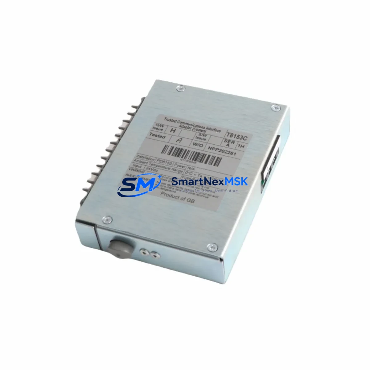
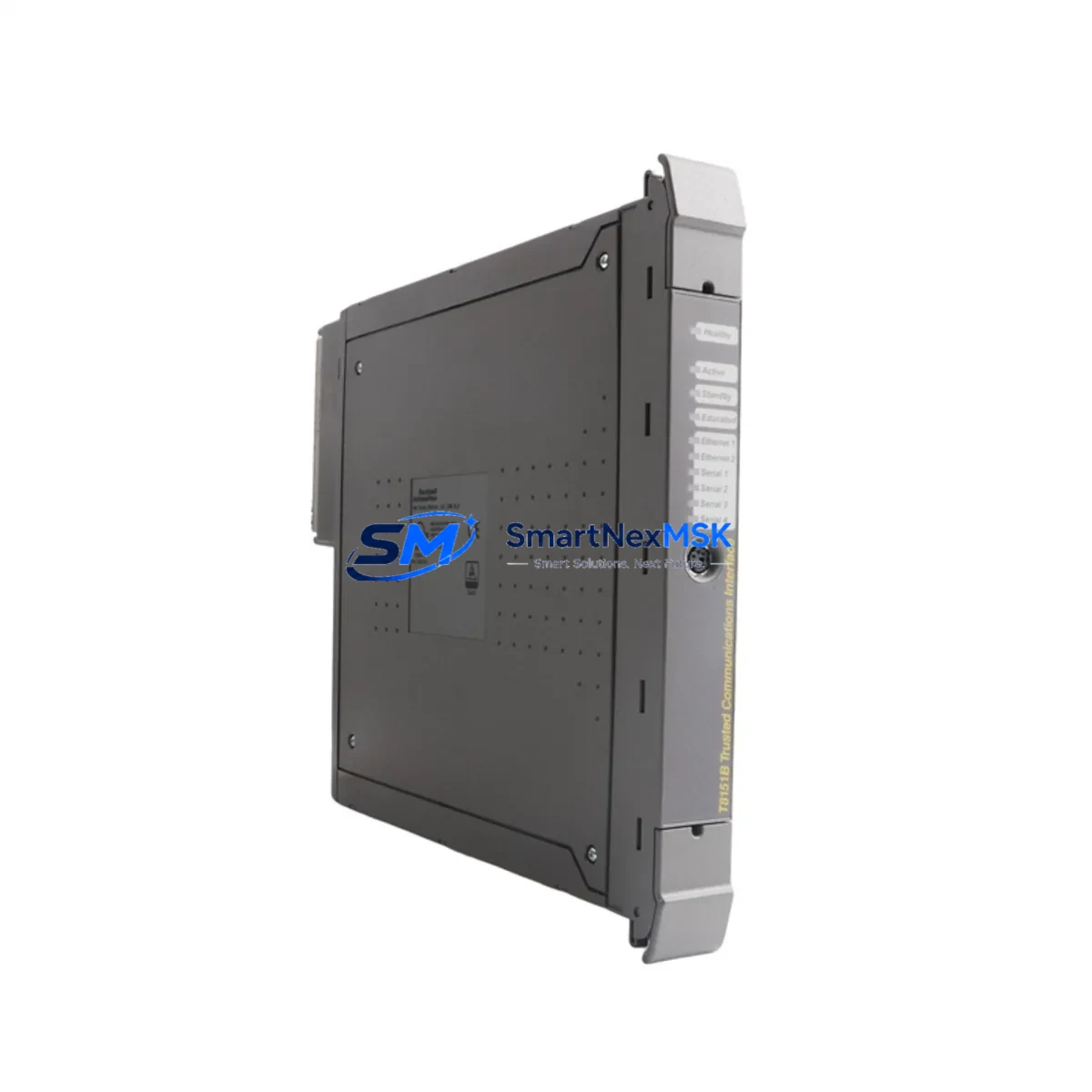
The ICS TRIPLEX T8151C is an original Communications Interface Module designed for the T8000 Series Triple Modular Redundancy (TMR) safety system. As a critical node in high-availability process control architectures, the T8151C manages inter-module communication within the T8000 chassis, ensuring continuous data exchange between the processor, I/O modules, and supervisory systems. When this module fails or degrades, the entire safety loop is at risk — making a verified, tested spare unit an essential element of any maintenance-ready inventory strategy.
For maintenance engineers operating in petrochemical, oil & gas, power generation, or continuous process industries, the T8151C is not a component that can be improvised or substituted with an unverified alternative. Its role in TMR voting logic and fault-tolerant communication demands an original, factory-specification replacement. This listing provides a genuine ICS TRIPLEX T8151C, sourced, inspected, and dispatched with a 12-month warranty — ready for immediate site deployment.
Spare Maintenance Table
| Parameter | Specification / Detail |
|---|---|
| Part Number | T8151C |
| Manufacturer | ICS TRIPLEX |
| Series | T8000 TMR Safety System |
| Module Type | Communications Interface Module |
| System Compatibility | ICS TRIPLEX T8000 Series TMR chassis; compatible with T8110, T8120, T8131, T8140 processor and I/O modules |
| Communication Protocol | Proprietary T8000 inter-module bus; supports supervisory SCADA/DCS integration |
| Operating Voltage | 24 VDC (supplied via T8000 backplane) |
| Operating Temperature | 0°C to +60°C |
| Mounting | T8000 Series chassis backplane slot |
| Weight | 920 g |
| Origin | Germany |
| Condition | Original, tested, fully functional |
| Pre-shipment Test | Full functional verification prior to dispatch |
| Warranty | 12 Months |
| Lead Time | In stock — ships within 2 business days |
| Application Environment | Safety-critical process control: oil & gas, petrochemical, power generation, chemical processing |
| Maintenance Recommendation | Inspect communication bus integrity and backplane connector condition at each planned shutdown; replace proactively at first sign of intermittent fault codes |
Maintenance Planning for Continuous Operation
When a T8151C Communications Interface Module is flagged for replacement — whether through diagnostic fault codes, communication timeouts, or scheduled lifecycle management — the replacement event is an opportunity to conduct a broader inspection of the T8000 control cabinet. Experienced maintenance engineers know that a failing communications module rarely operates in isolation; adjacent components in the same electrical circuit and communication loop are often under similar stress.
Begin with the T8000 chassis backplane itself. Backplane connector wear and oxidation are common causes of intermittent communication faults that are incorrectly attributed to the T8151C module. Inspect and clean backplane contacts before installing the replacement unit. At the same time, verify the condition of the T8110 or T8120 Processor Module — communication errors logged against the T8151C may originate from processor-side bus faults rather than the interface module itself.
Review the T8140 I/O Modules connected to the same communication bus. A degraded I/O module can generate bus contention that accelerates wear on the T8151C. If the system includes a T8131 Digital Input Module or T8132 Digital Output Module in the same voting loop, inspect their status LEDs and diagnostic registers during the maintenance window. Replacing the T8151C without verifying I/O module health risks a repeat fault within weeks.
Power supply integrity is equally critical. The T8000 system relies on redundant 24 VDC power feeds; inspect the T8800 Power Supply Module for output ripple and voltage stability. A marginal power supply is a leading cause of premature communications module failure. Check fuse holders and terminal blocks on the power distribution rail — corroded terminals introduce resistance that manifests as erratic module behavior.
For systems with SCADA or DCS integration, verify the communication gateway or serial interface converter connected to the T8151C output. Signal isolators on the supervisory communication line should be tested for isolation resistance and signal integrity. If the plant uses a Modbus or HART signal path through this cabinet, inspect the signal isolator modules and surge protection devices on those lines as part of the same maintenance event.
Finally, review the HMI panel connected to the T8000 system. HMI communication loss is often the first symptom reported by operators when a T8151C begins to degrade. Confirming HMI communication is restored after module replacement — and logging the baseline communication response time — provides a measurable benchmark for future condition monitoring.
Site Replacement Workflow
Step 1 — Pre-replacement documentation: Record all active fault codes and communication status from the T8000 system diagnostic interface. Photograph the existing T8151C module position, wiring, and any jumper or DIP switch settings before removal.
Step 2 — Safe isolation: Follow site-specific lock-out/tag-out (LOTO) procedures. The T8000 TMR architecture allows hot-swap of certain modules in redundant configurations — confirm with your system documentation whether the T8151C in your chassis supports live replacement or requires a controlled shutdown.
Step 3 — Module extraction: Release the module retention latch and extract the T8151C from its backplane slot. Inspect the backplane connector pins for damage or contamination before inserting the replacement unit.
Step 4 — Replacement installation: Insert the new T8151C firmly into the designated slot until the retention latch engages. Verify the module’s status LED sequence on power-up matches the expected initialization pattern described in the T8000 system manual.
Step 5 — Communication verification: Confirm communication restoration via the T8000 diagnostic interface and the connected HMI or SCADA system. Clear historical fault codes and monitor for recurrence over the first 30 minutes of operation.
Step 6 — Documentation update: Record the replacement in the site maintenance log, including the new module serial number, installation date, and post-replacement diagnostic status. Update the spare parts inventory to trigger reorder of a replacement T8151C for the next maintenance cycle.
This workflow minimizes downtime, maintains system compatibility, and ensures the T8000 TMR safety system returns to full operational status with a verified, documented replacement history.
Spare Parts Support FAQ
Q1: Is this T8151C an original ICS TRIPLEX module or a third-party compatible replacement?
This is a genuine, original ICS TRIPLEX T8151C Communications Interface Module — not a clone, refurbished third-party unit, or compatible substitute. Each unit is sourced from verified supply channels and undergoes functional testing prior to dispatch. The 12-month warranty covers full replacement in the event of any verified manufacturing or functional defect.
Q2: How do I confirm compatibility with my specific T8000 chassis revision?
The T8151C is designed for the ICS TRIPLEX T8000 Series TMR platform. Compatibility depends on your chassis revision and firmware version. We recommend providing your chassis model number and current firmware revision when placing your order so our technical team can confirm fit before shipment. Pre-shipment functional testing is performed on all units.
Q3: What is the recommended spare parts stocking strategy for the T8151C?
For safety-critical TMR systems, industry best practice recommends maintaining a minimum of one cold-standby T8151C per installed system. For plants with multiple T8000 systems or extended lead-time risk, a two-unit buffer is advisable. Given the end-of-production status of many T8000 Series components, long-term supply availability should be factored into your lifecycle planning. We offer long-term supply agreements for customers requiring guaranteed stock availability.
Q4: What does the 12-month warranty cover, and what is the return process?
The 12-month warranty covers functional failure under normal operating conditions consistent with the T8000 system specification. It does not cover damage resulting from incorrect installation, overvoltage events, or use outside the specified environmental range. In the event of a warranty claim, contact our technical team with the fault description and installation documentation. Replacement units are dispatched after fault verification, with return shipping coordinated by our logistics team.
© 2026 SMARTNEXMSK. All rights reserved.
Original Source: https://smartnexmsk.com
Contact: sales@smartnexmsk.com | +86 18259474341