ICS Triplex T8830C Retrofit-Ready Field Termination Assembly for Trusted Control Systems
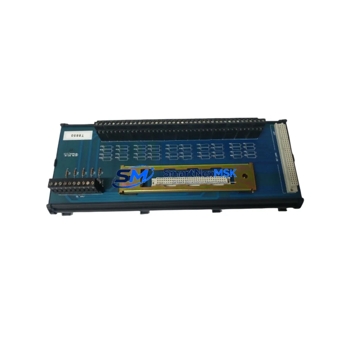
The ICS Triplex T8830C is a 40-channel Analogue Input Field Termination Assembly (FTA) engineered for seamless integration within the ICS Triplex Trusted Series safety and control platform. As legacy Trusted Series installations approach end-of-life or require capacity expansion, the T8830C serves as the definitive retrofit solution — enabling engineers to restore full analogue I/O functionality without redesigning the control architecture or replacing the primary controller.
Whether you are replacing a failed unit on a live production line, upgrading a brownfield facility, or migrating from an older Trusted T8800-series FTA variant, the T8830C delivers the electrical compatibility, terminal layout, and signal conditioning characteristics required for a controlled, low-risk changeover. Its 40-channel density makes it particularly valuable in process industries where analogue loop counts are high and panel space is constrained.
Upgrade Compatibility Table
| Parameter | Detail |
|---|---|
| Model | ICS Triplex T8830C |
| Function | 40-Channel Analogue Input Field Termination Assembly |
| Compatible Platform | ICS Triplex Trusted Series (TMR Safety Controller) |
| Replaces / Upgrades | T8830, T8830A, T8830B (earlier FTA revisions) |
| Backplane Interface | Trusted Series standard FTA backplane connector |
| Signal Type | 4–20 mA analogue input (HART-compatible loops) |
| Terminal Wiring | Screw-terminal field wiring; compatible with existing cable schedules |
| Installation | DIN-rail / panel mount; same footprint as predecessor revisions |
| Communication Compatibility | Trusted TMR backplane bus; no protocol reconfiguration required |
| Commissioning Note | Verify module address assignment in Trusted Toolset after swap |
| Firmware / Software | No firmware update required on FTA; validate I/O map in application logic |
| Warranty | 12 Months — covers manufacturing defects and functional verification |
Retrofit Planning for Existing Automation Systems
A successful T8830C retrofit begins well before the physical swap. Engineers should start by auditing the existing Trusted T8110 TMR Controller configuration to confirm available FTA slots on the Trusted Series chassis and verify that the backplane power budget accommodates the T8830C’s current draw alongside co-installed modules such as the T8461 Digital Output FTA and T8451 Digital Input FTA. Power supply headroom is a common oversight — the T8920 Power Supply Module feeding the rack should be load-tested before the new FTA is energised.
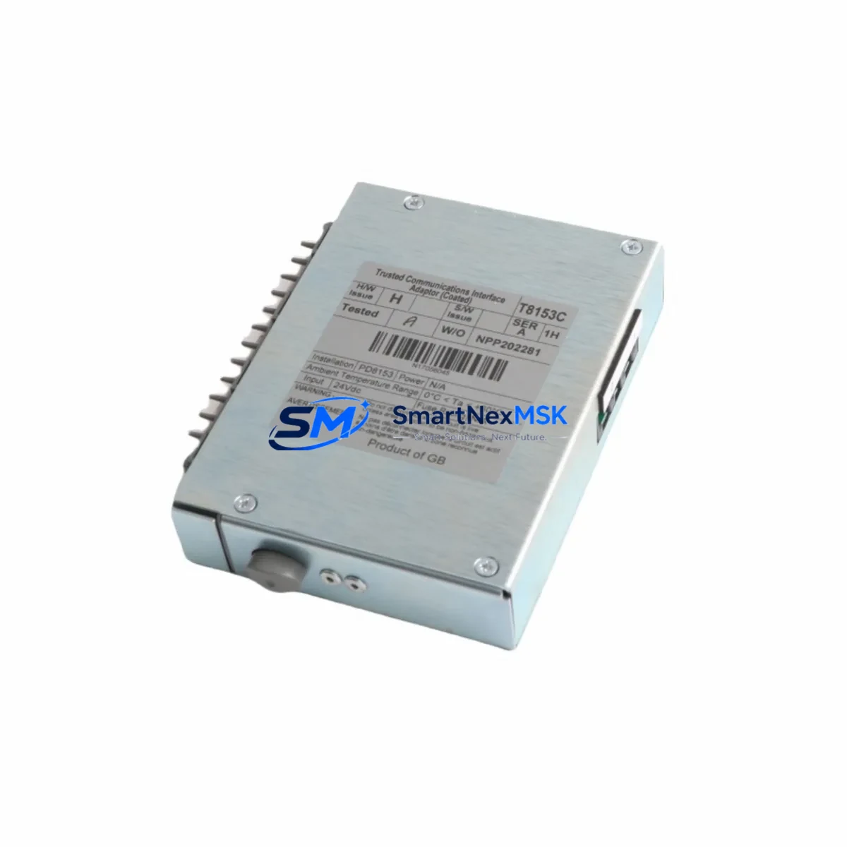
Terminal wiring is the next critical checkpoint. The T8830C uses the same screw-terminal field wiring convention as earlier T8830-series assemblies, so existing cable schedules and loop drawings typically remain valid. However, field engineers should perform a point-to-point continuity check on all 40 analogue loops before powering up, paying particular attention to shield grounding and loop isolation where HART-enabled transmitters are in service. If the plant uses a Trusted T8310 Communication Module for Modbus or PROFIBUS integration, confirm that the analogue channel address map in the communication configuration matches the new FTA’s slot assignment.
Module addressing is managed through the ICS Triplex Trusted Toolset engineering workstation software. After physical installation, connect via the T8920 programming cable or the dedicated engineering port on the T8110 controller, navigate to the I/O configuration tree, and confirm that the T8830C is recognised at the correct rack position. If the application program references analogue input tags by absolute I/O address, no logic changes are required. If symbolic addressing is used, verify that the tag-to-channel mapping is intact before releasing the system to automatic control.
HMI screens connected via the Trusted Series OPC DA/UA server or a third-party SCADA platform should be validated in simulation mode prior to live cutover. Analogue trend displays, alarm setpoints, and engineering-unit scaling configured against the original T8830 channels will carry forward without modification, provided the channel order is preserved. Where a T8840 Analogue Output FTA is co-located in the same control loop, confirm that the output channel’s feedback path reads correctly from the newly installed input assembly.
All units supplied by SMARTNEXMSK are subject to pre-shipment functional testing, including channel-by-channel signal injection across the 4–20 mA range, backplane connector inspection, and visual quality control. Each T8830C ships with a test report and is covered by a 12-month warranty against manufacturing defects.
Downtime Control During System Migration
Minimising unplanned downtime during a Trusted Series FTA replacement requires a structured hot-swap or controlled-outage procedure. Where the plant safety case permits, the Trusted TMR architecture’s triple-redundant voting logic allows a single FTA to be removed and replaced while the remaining two channels maintain process control — consult your site-specific safety instrumented system (SIS) bypass procedure before proceeding.
For non-redundant analogue input channels, the recommended approach is to schedule the swap during a planned maintenance window. Before de-energising the FTA, capture a snapshot of all 40 analogue process values from the SCADA historian or the Trusted Toolset online monitor. This baseline serves as the acceptance criterion after reinstatement — if all channels return to within ±0.1% of the pre-swap readings under identical process conditions, the retrofit is confirmed successful.
Original application logic stored in the T8110 controller is unaffected by an FTA swap; the program image resides in the controller’s non-volatile memory and does not require re-download. However, if the outage window also includes a firmware update to the controller or a revision to the application program, ensure that the updated program is compiled, peer-reviewed, and staged on the engineering workstation before the maintenance window opens. Combining a hardware swap with a software change in a single outage is efficient but requires disciplined change management to isolate root causes if post-restart issues arise.
Field teams should have the following items staged before the outage begins: the replacement T8830C unit, a calibrated loop calibrator for post-installation signal verification, a copy of the current I/O schedule, the Trusted Toolset laptop with the correct project file loaded, and the site’s SIS bypass log. With these preparations in place, a single-FTA swap can typically be completed and verified within a two-hour maintenance window.
Retrofit Support FAQ
Q1: Is the T8830C a direct drop-in replacement for the T8830 and T8830A?
Yes. The T8830C is the current production revision of the T8830 analogue input FTA family. It shares the same backplane connector, terminal block layout, and channel count as earlier revisions. No mechanical modifications to the panel or cable schedule are required. Confirm the revision compatibility note in the Trusted Series hardware manual for your specific controller firmware version.
Q2: What commissioning steps are required after installation?
After seating the T8830C in the chassis, connect the Trusted Toolset engineering workstation and verify that the module is recognised at the correct rack/slot address. Perform a channel-by-channel loop check using a 4–20 mA calibrator. Confirm that analogue values display correctly in the SCADA or DCS operator station. Release the system from bypass only after all 40 channels have been verified within calibration tolerance.
Q3: Can the T8830C be used with HART-enabled field instruments?
Yes. The T8830C supports HART communication superimposed on the 4–20 mA analogue signal. A HART multiplexer or handheld communicator can be connected to individual loop terminals for device configuration and diagnostics without interrupting the primary analogue signal path.
Q4: What does the 12-month warranty cover?
The 12-month warranty covers manufacturing defects, component failures under normal operating conditions, and functional non-conformance identified during incoming inspection. Each unit is pre-tested prior to shipment. Warranty claims are supported by SMARTNEXMSK’s technical team — contact sales@smartnexmsk.com with the unit serial number and a description of the fault. Physical damage caused by incorrect installation, overvoltage, or environmental exposure is excluded.
© 2026 SMARTNEXMSK. All rights reserved.
Original Source: https://smartnexmsk.com
Contact: sales@smartnexmsk.com | +86 18259474341