ICS Triplex T8461 Retrofit-Ready DO Module for TMR Systems: Seamless Compatibility for Legacy Control System Upgrades
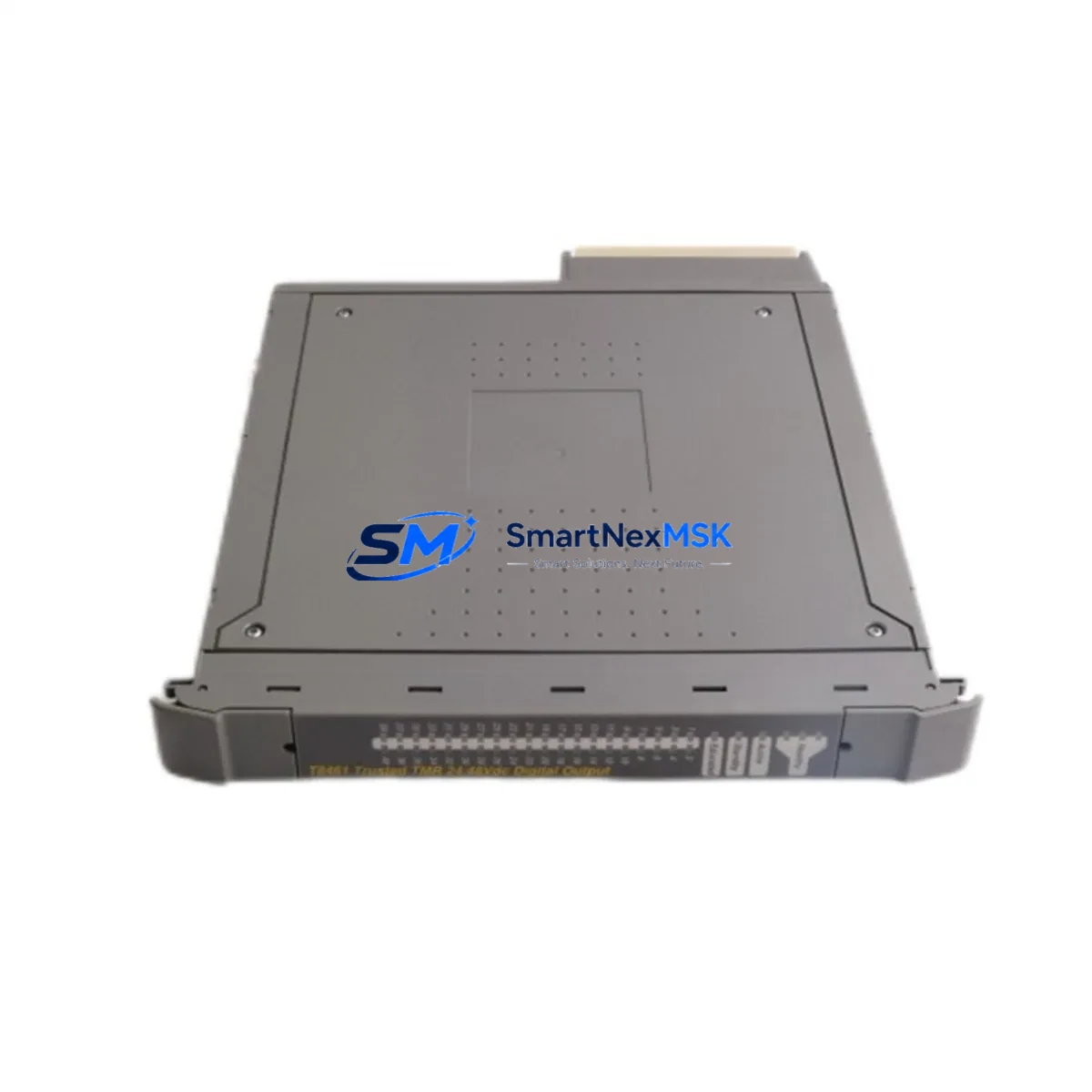
The ICS Triplex T8461 is a 24/48V DC Digital Output Module purpose-built for the Trusted TMR (Triple Modular Redundancy) Series safety control platform. As legacy TMR installations age and original spare parts become increasingly scarce, the T8461 has become a critical component in plant-wide retrofit programs, emergency spare strategies, and phased control system modernization projects. Whether you are replacing a failed module in a live safety loop or planning a structured migration from an end-of-life DCS to a current-generation SIS, the T8461 delivers the output drive capacity, voting architecture compatibility, and backplane interface integrity that TMR applications demand.
Our inventory of the T8461 is sourced, inspected, and dispatch-tested before shipment. Each unit undergoes functional verification covering channel isolation, output switching response, and diagnostic register behavior. A 12-month warranty is included with every shipment, covering manufacturing defects and functional failures under normal operating conditions. Global logistics from our Xiamen facility supports urgent plant requirements with short lead times.
Upgrade Compatibility Table
| Parameter | T8461 Specification | Retrofit Notes |
|---|---|---|
| Module Type | Digital Output, 24/48V DC | Direct replacement for same-series DO slots |
| Platform Compatibility | ICS Triplex Trusted TMR Series | Verify chassis generation before installation |
| Backplane Interface | TMR proprietary backplane bus | Confirm slot address and rack position with existing I/O map |
| Output Channels | 16-channel DO (application-dependent) | Channel-for-channel mapping required during wiring adaptation |
| Communication Protocol | Internal TMR voting bus | No protocol migration needed for same-platform replacement |
| Power Supply Compatibility | 24V DC / 48V DC field power | Verify field power rail capacity before hot-swap or cold replacement |
| Terminal Wiring | Marshalling terminal block via T8100-series I/O termination | Retain existing termination assembly; no rewiring required for drop-in swap |
| Module Address | Slot-based addressing via TMR chassis | Address inherited from slot position; no DIP switch configuration required |
| Program Compatibility | Fully compatible with existing Trusted application logic | No application download required for same-type replacement |
| Diagnostic Support | Online diagnostics via Trusted ToolSuite | Confirm diagnostic channel mapping post-installation |
| Warranty | 12 Months | Covers functional failure under normal operating conditions |
Retrofit Planning for Existing Automation Systems
Replacing the T8461 within an operational TMR safety system requires a structured approach that accounts for the interdependencies of the Trusted platform architecture. The TMR chassis — typically a T8110 series rack — houses the processor modules, power supply modules, and I/O modules in a tightly integrated voting arrangement. Before removing the T8461, engineers should confirm that the T8110 chassis backplane is free of corrosion or connector damage, as backplane integrity directly affects the new module’s ability to participate in the 2-out-of-3 voting logic.
Field power for the digital output channels is typically sourced from a dedicated 24V DC or 48V DC power distribution rail within the control cabinet. Before installation, verify that the power supply module — such as the T8150 or T8151 redundant power supply unit — is delivering stable voltage within specification. An undersized or degraded power supply can cause intermittent output faults that are difficult to distinguish from module failures during commissioning. Where the control cabinet also houses a T8800 Trusted Communications Module for Modbus or PROFIBUS connectivity, confirm that the communications link remains stable throughout the swap procedure to avoid spurious alarms at the SCADA level.
Terminal wiring for the T8461 is routed through the associated I/O termination assembly, often a T8100-series marshalling panel. In most retrofit scenarios, the termination assembly remains in place and the module is swapped without disturbing field wiring. This significantly reduces the risk of wiring errors and shortens the replacement window. However, if the termination assembly itself is aged or if the project involves migrating from a different I/O architecture, a full terminal-by-terminal verification against the as-built drawings is mandatory before energizing the new module.
For projects that involve migrating from a legacy Triconex TRICON or Honeywell Safety Manager platform to the ICS Triplex Trusted TMR architecture, the T8461 is typically introduced as part of a broader I/O replacement strategy. In these cases, the T8800 communications module must be configured to reflect the updated I/O map, and the HMI tag database in the associated SCADA or DCS — for example, a Yokogawa CENTUM VP or ABB 800xA system — must be updated to reflect the new module addresses and channel assignments. Failure to synchronize the HMI tag database with the new I/O configuration is one of the most common causes of extended commissioning delays in cross-platform migration projects. Where the existing HMI is a legacy Wonderware InTouch or Siemens WinCC installation, plan for a dedicated tag re-mapping session as part of the cutover schedule.
Where the retrofit involves expanding the I/O count — for example, adding new field devices to an existing safety loop — the T8461 can be installed in a previously empty slot within the existing T8110 chassis, provided the chassis has available capacity and the application program has been updated to include the new output channels. The Trusted ToolSuite engineering workstation software is used to download the updated application and verify channel assignments before the new outputs are placed in service. If the chassis is already at full capacity, a chassis expansion using an additional T8110 rack and the appropriate T8100-series backplane extension cable may be required before the T8461 can be added.
Downtime Control During System Migration
Minimizing unplanned downtime during a T8461 replacement or TMR system upgrade requires careful pre-staging and a clearly defined cutover sequence. The TMR architecture’s inherent redundancy allows a single module to be removed and replaced while the remaining two legs of the voting triad continue to maintain output integrity — provided the system is not already in a degraded state. Before initiating any module swap, confirm the health status of all three legs using the Trusted ToolSuite diagnostic interface. A system already operating in 2-out-of-3 mode due to a prior fault in another module — such as a failed T8431 Digital Input Module or a degraded T8150 power supply — should not undergo a second module replacement without a formal risk assessment and, where required, a controlled process shutdown.
To protect the original application logic during the replacement, export and archive the current application program from the Trusted ToolSuite before any hardware changes are made. This ensures that if the replacement module requires a fresh application download — for example, due to firmware version differences between the outgoing and incoming T8461 units — the correct program version is immediately available without delay. In most same-type, same-firmware replacements, no application download is required, and the module will synchronize automatically with the running application after insertion into the T8110 chassis.
Field control continuity during the cutover window can be maintained by placing the affected output channels in a defined safe state — typically de-energized — before the module is removed. Coordinate with the process control team and the safety instrumented system (SIS) engineer to confirm that placing the outputs in a safe state does not trigger an unintended process trip or interlock activation. Document the pre-swap channel states and restore them in sequence after the new T8461 has been installed and verified online. Post-installation, run a full channel-by-channel output test using the Trusted ToolSuite forced output function before returning the module to automatic control. Where the plant uses a T8800 communications module to relay output status to a remote DCS, verify that the communications link is re-established and that all output status tags are reading correctly at the operator workstation before closing out the work order.
Retrofit Support FAQ
Q1: Is the T8461 a direct drop-in replacement for the original ICS Triplex T8461 installed in my TMR chassis?
Yes. The T8461 is a same-type replacement and is designed to install directly into the original slot without modifications to the backplane, termination assembly, or application program. Confirm that the firmware version of the replacement module is compatible with your chassis firmware before installation. If a firmware update is required, this can be performed using the Trusted ToolSuite prior to module insertion. All units shipped by SMARTNEXMSK are dispatch-tested and include a functional test report on request.
Q2: What wiring and power checks are required before installing the T8461?
Verify that the field power rail supplying the output channels is within the specified 24V DC or 48V DC range and that the current capacity of the power distribution circuit — typically fed from the T8150 or T8151 redundant power supply — is sufficient for the connected field devices. Inspect the T8100-series termination assembly connector for pin damage or oxidation. If the termination assembly has been in service for more than ten years, consider replacing the connector housing as part of the retrofit to prevent intermittent contact faults after the new module is installed.
Q3: Can the T8461 be used in a cross-platform migration from a Triconex or Honeywell Safety Manager system?
The T8461 is specific to the ICS Triplex Trusted TMR platform and is not directly interchangeable with Triconex TRICON or Honeywell Safety Manager I/O modules. In a cross-platform migration, the T8461 is installed as part of a new Trusted chassis assembly, and the application logic must be re-engineered in the Trusted ToolSuite. Field wiring can often be reused if the terminal block layout is adapted to the T8100-series termination assembly format. The T8800 communications module will also need to be reconfigured to match the new I/O map and communication protocol requirements of the target DCS or SCADA system.
Q4: What does the 12-month warranty cover, and what is the process for a warranty claim?
The 12-month warranty covers functional failures attributable to manufacturing defects under normal operating conditions. It does not cover damage resulting from incorrect installation, overvoltage, reverse polarity, or physical impact. To initiate a warranty claim, contact our sales team with the module serial number, purchase order reference, and a description of the observed fault. We will arrange return logistics and provide a replacement or repaired unit within an agreed lead time to minimize your plant downtime.
© 2026 SMARTNEXMSK. All rights reserved.
Original Source: https://smartnexmsk.com
Contact: sales@smartnexmsk.com | +86 18259474341