KUKA 00-150-553 Retrofit-Ready Servo Drive for KRC Control Systems: Compatible Modernization & Smooth Legacy Upgrade
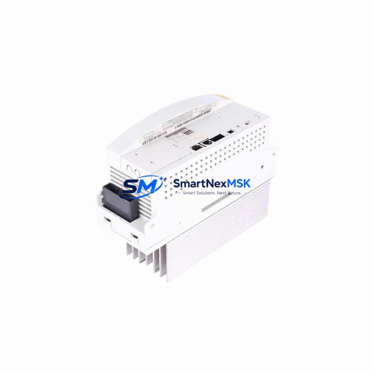
The KUKA 00-150-553 is a servo drive module engineered for deployment within KUKA KRC-series robot control cabinets, most commonly the KRC2 platform. As KUKA progressively phases out legacy KRC2 components, end-users operating older robotic cells face increasing pressure to source reliable replacement units or plan structured migration paths toward KRC4 or KRC5 architectures. The 00-150-553 addresses both scenarios: it serves as a direct drop-in replacement for failed or end-of-life servo drive assemblies, and it forms a critical building block in phased retrofit programs where full controller replacement is not yet feasible.
This module governs axis-level power conversion and motion control within the KRC2 cabinet, interfacing directly with the KPS600 power supply unit and communicating with the KRC2 main computer board via the internal KUKA System Bus (KSB). When replacing a failed unit, engineers must verify that the cabinet’s KPS600 or KPS27 power supply is delivering correct DC bus voltage before installation, as an upstream power fault is frequently the root cause of servo drive failure. Confirming bus voltage stability before fitting the 00-150-553 prevents repeat failures and protects the new module.
Terminal wiring on the 00-150-553 follows the standard KRC2 axis connector pinout. Technicians migrating from an older revision of this drive should cross-reference the motor power connector (X1–X6 axis assignments), the resolver or encoder feedback connector, and the brake control lines. In multi-axis cabinets running A1 through A6 plus external axes, each drive slot is addressed by the KRC2 controller through a fixed module address determined by physical slot position on the backplane — no software address configuration is required, which simplifies hot-swap procedures during planned maintenance windows.
For sites running KUKA System Software (KSS) versions 4.x or 5.x, program compatibility is maintained at the RAPID/KRL language level. Existing robot programs, tool data, base frames, and safety configurations stored on the KRC2 hard drive or CompactFlash card are unaffected by a servo drive swap. However, if the retrofit scope extends to replacing the KRC2 main computer or upgrading to a KRC4 controller with VxWorks-based KSS 8.x, a full program migration and HMI screen reconfiguration on the KUKA smartPAD teach pendant will be required. In such cases, retaining a verified backup of the KSS archive before any hardware change is non-negotiable.
Upgrade Compatibility Table
| Parameter | Detail |
|---|---|
| Compatible Controller | KUKA KRC2, KRC2 ed05 |
| Replaces / Supersedes | Earlier 00-1xx-xxx KRC2 servo drive revisions |
| Backplane Interface | KRC2 internal bus (KSB), slot-addressed |
| Power Supply Compatibility | KPS600 / KPS27 DC bus |
| Communication Protocol | KUKA System Bus (KSB); DeviceNet / PROFIBUS via optional CMR/CCU board |
| Motor Feedback | Resolver / RDC board compatible |
| Installation Type | Direct slot replacement — no mechanical modification |
| Axis Coverage | A1–A6 + external axis (E1) depending on slot assignment |
| Commissioning Requirement | Mastering (zero-point calibration) after replacement |
| Warranty | 12 months from date of shipment |
Retrofit Planning for Existing Automation Systems
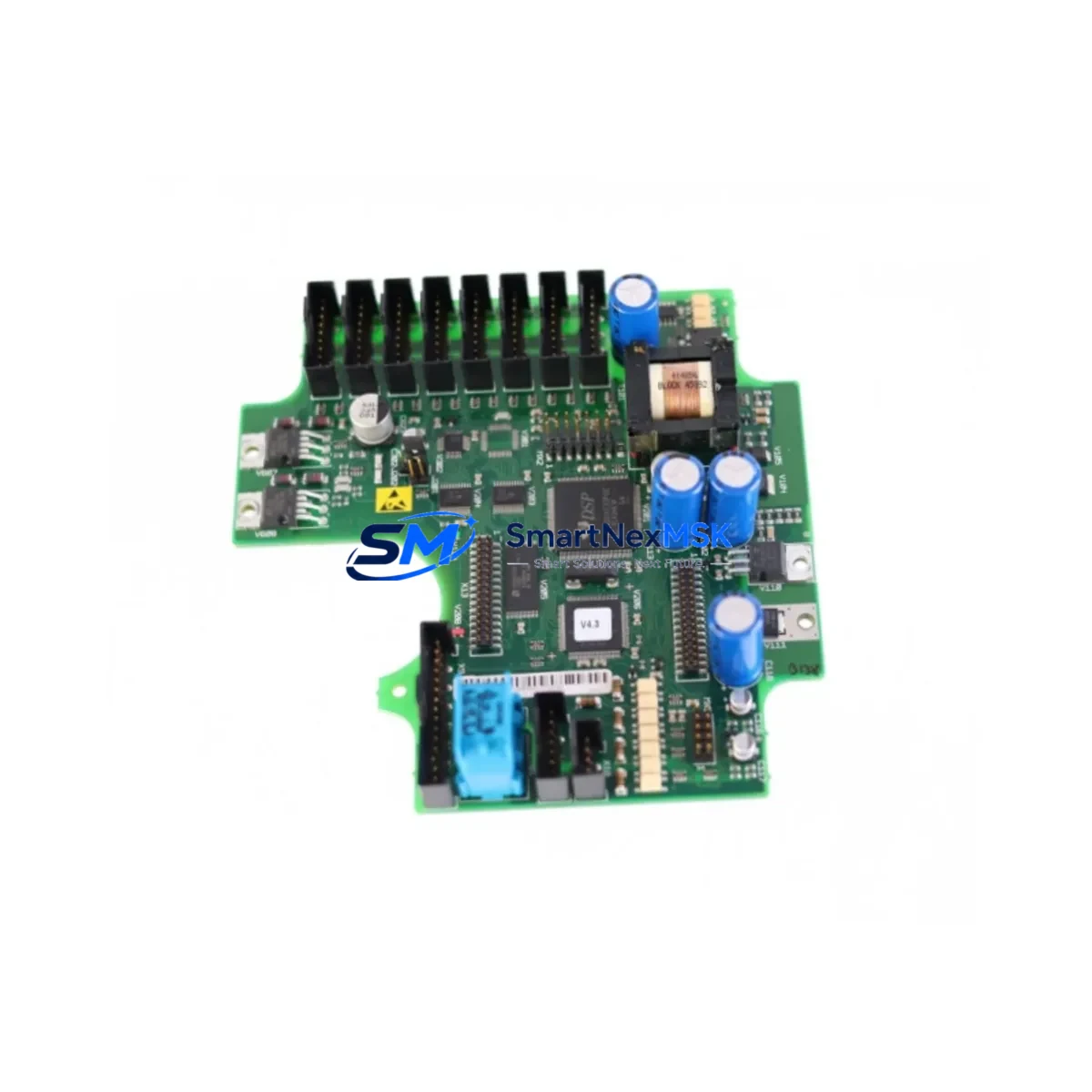
A structured retrofit begins with a full audit of the KRC2 cabinet’s component health. Beyond the servo drive itself, the KPS600 power supply module, the KRC2 main computer board, and the RDC (Resolver-to-Digital Converter) board are the components most likely to require concurrent attention in aging systems. If the RDC board shows resolver signal errors in the KSS error log, replacing the 00-150-553 alone will not restore full axis functionality — the RDC board must be addressed in parallel.
Communication infrastructure is equally important. Sites using PROFIBUS-DP for PLC integration — for example, connecting the KRC2 to a Siemens S7-300 or S7-400 controller via a CP 342-5 communications processor — must verify that the PROFIBUS address and GSD file configuration remain intact after any hardware change. Similarly, installations using DeviceNet via a KUKA CCU (Cabinet Control Unit) board should confirm node addressing before returning the robot to automatic mode. If the retrofit roadmap includes migrating to PROFINET, a KRC4 controller with an integrated PROFINET interface card will be required, along with updated network topology planning.
For I/O-intensive applications, the KRC2’s digital I/O capacity is typically extended through a KUKA KIO (KUKA I/O) module or through a fieldbus-connected remote I/O rack. During a servo drive replacement, I/O mapping should be verified against the robot program’s signal table to ensure no address conflicts have been introduced. End-of-arm tooling signals routed through the robot’s internal cable harness (X11 connector) should also be continuity-tested as part of the post-replacement checkout.
Where the retrofit scope includes upgrading the teach pendant, sites moving from the legacy KCP2 pendant to the KUKA smartPAD must account for the different connector type and updated safety interface. The smartPAD is not backward-compatible with KRC2 without an adapter kit, so pendant upgrades are typically deferred to a full KRC4 migration rather than a component-level KRC2 repair.
Downtime Control During System Migration
Minimizing unplanned downtime during a servo drive replacement requires pre-staging the replacement 00-150-553 unit, verifying it against the cabinet’s serial number and KSS version documentation before the maintenance window opens. A pre-tested, bench-verified unit eliminates the risk of discovering a compatibility issue after the production line has been stopped.
Before powering down the KRC2 cabinet, technicians should perform a full KSS archive backup to an external USB drive or network share, capturing robot programs, system configuration, tool/base data, and safety parameters. This archive is the single most important asset for rapid recovery if the replacement procedure encounters an unexpected complication.
After fitting the 00-150-553, the standard recommissioning sequence involves: restoring cabinet power, confirming no new fault codes on the KSS status display, performing axis mastering using the KUKA Electronic Mastering Device (EMD) or dial gauge method, and running a slow-speed test cycle through the full working envelope before returning to production speed. For cells with external safety PLCs — such as a Pilz PNOZ or a Siemens ET 200SP fail-safe CPU — the safety handshake signals between the KRC2 safety interface board and the external safety controller must be verified before enabling automatic mode. Total planned downtime for a straightforward servo drive swap in a well-documented KRC2 cell typically ranges from two to four hours, including mastering and test cycles.
Retrofit Support FAQ
Q: Is the KUKA 00-150-553 a direct replacement for all KRC2 servo drive variants?
A: The 00-150-553 is compatible with standard KRC2 and KRC2 ed05 cabinets. Compatibility with specific axis slots (A1–A6, E1) depends on the original cabinet configuration. We recommend providing your cabinet serial number and KSS version when ordering to confirm exact fitment.
Q: Will I need to reprogram the robot after replacing the servo drive?
A: No. A servo drive replacement does not affect stored KRL programs, tool data, or base frames. However, axis mastering (zero-point calibration) is required after any servo drive or motor replacement. Retain a full KSS archive backup before beginning work as a standard precaution.
Q: What wiring checks are required before installation?
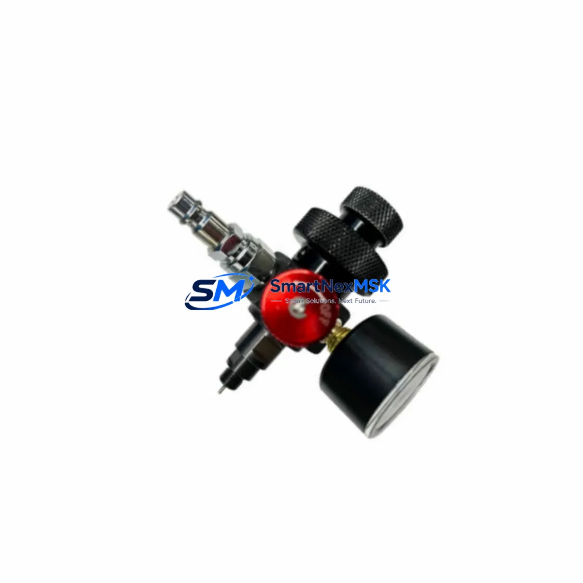
A: Verify DC bus voltage from the KPS600 power supply, inspect motor power connectors (X1–X6) for pin damage or corrosion, and confirm resolver feedback cable continuity. Check brake control wiring for the affected axis. Any wiring anomaly should be resolved before fitting the new module to prevent repeat failure.
Q: What does the 12-month warranty cover?
A: All units ship with a 12-month warranty from the date of shipment, covering manufacturing defects and functional failure under normal operating conditions. Each unit undergoes pre-shipment functional testing. Warranty claims are supported directly by our technical team at sales@smartnexmsk.com.
© 2026 SMARTNEXMSK. All rights reserved.
Original Source: https://smartnexmsk.com
Contact: sales@smartnexmsk.com | +86 18259474341