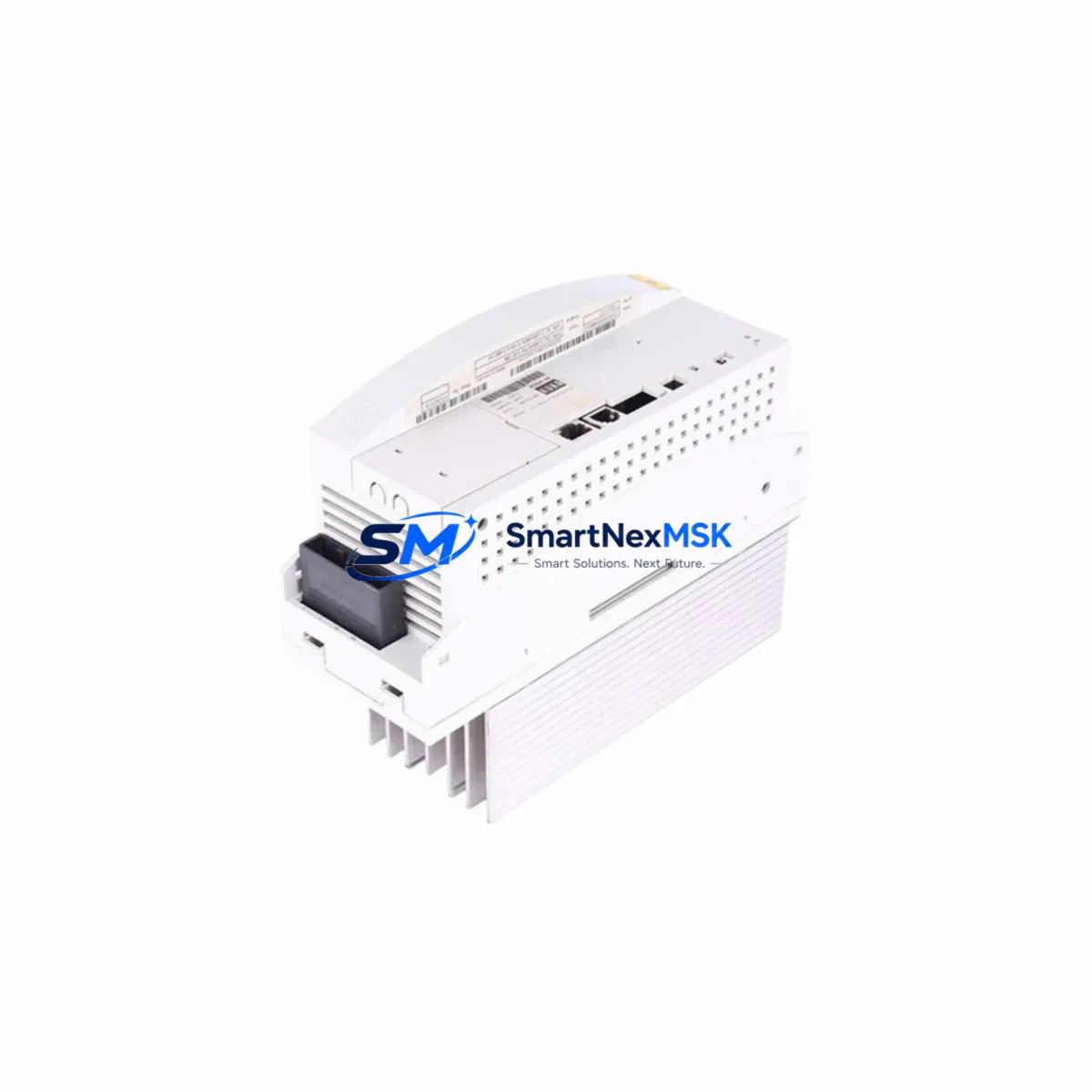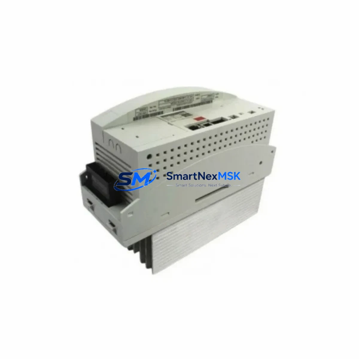
KUKA 00-169-213 Retrofit-Ready DC Power Module for KRC4 Control Systems
The KUKA 00-169-213 is a DC power supply module engineered for the KRC4 robot controller cabinet, delivering a regulated 27V / 40A output to sustain the full servo drive chain, safety relay circuits, and fieldbus communication nodes within the KRC4 enclosure. As KUKA progressively phases out legacy KRC2 and early KRC4 hardware, end-users operating KUKA KR 6, KR 10, KR 16, KR 30, and KR 60 robot cells increasingly rely on verified replacement units like the 00-169-213 to maintain production continuity without committing to a full controller overhaul.
Whether you are executing a planned cabinet refurbishment, recovering from an unplanned power-module failure, or migrating a multi-robot cell from KRC2 to KRC4 architecture, the 00-169-213 provides a direct, wiring-compatible drop-in solution. Each unit shipped by SMARTNEXMSK undergoes functional load testing at rated current before dispatch, and is covered by a 12-month warranty against manufacturing defects.
Upgrade Compatibility Table
| Parameter | KUKA 00-169-213 (This Unit) | Notes / Retrofit Guidance |
|---|---|---|
| Output Voltage | 27 V DC | Matches KRC4 internal bus standard; no voltage adjustment required |
| Rated Output Current | 40 A | Verify total cabinet load does not exceed 38 A continuous (10% derating recommended) |
| Input Voltage Range | AC 200–240 V, 50/60 Hz | Confirm site supply voltage before installation; use isolation transformer if supply is unstable |
| Mounting Interface | KRC4 DIN-rail / backplane slot | Direct mechanical fit; no bracket modification needed for standard KRC4 cabinets |
| Terminal Wiring | Screw-terminal block, 6 mm² max | Re-use existing harness; inspect insulation and torque to 1.5 N·m per KUKA wiring spec |
| Communication Compatibility | Passive (power only) | No fieldbus address assignment required; EtherCAT / PROFINET topology unaffected |
| Replaces / Supersedes | Earlier KRC4 PSU variants | Cross-reference KUKA spare-parts list; confirm part number suffix matches cabinet revision |
| Commissioning Requirement | No software re-parameterization | Power-cycle KRC4 after swap; verify 27 V rail on KPS600 or KPP600 status LED |
| Warranty | 12 Months | Covers manufacturing defects; functional load test certificate available on request |
Retrofit Planning for Existing Automation Systems
A successful KRC4 power-module retrofit begins well before the maintenance window opens. Start by auditing the full cabinet bill of materials: the KPS600 primary power supply and KPP600 servo power pack share the 27 V bus with the 00-169-213, so their output ripple and load-sharing behavior must be verified after the swap. If the cabinet also houses a KSP600 servo inverter for external axes, confirm that the combined standby current draw remains within the new module’s derating curve at the site’s ambient temperature.
On the communication side, KRC4 cabinets running KUKA.EtherCAT or PROFINET fieldbus options route their 24 V logic supply through a secondary rail derived from the main 27 V bus. Replacing the 00-169-213 does not alter bus topology, but it is good practice to document the KUKA smartPAD HMI screen states and active safety-zone configurations before powering down, so that post-swap verification is systematic rather than reactive.
For cells integrating a KUKA KRC4 compact or KRC4 smallSize controller alongside a standard KRC4, ensure that the replacement power module revision is consistent across all cabinets sharing a common safety network. Mismatched firmware-dependent PSU revisions can trigger SafeOperation or SafeRangeMonitoring faults on the KUKA.SafeOperation option package. Where the original cabinet includes a KEB COMBIVERT or third-party servo drive on an auxiliary axis, verify that the 27 V auxiliary output connector pinout on the 00-169-213 matches the harness routed to that drive’s logic supply input.
If the retrofit scope extends to upgrading the teach pendant, note that transitioning from an older KCP2 pendant to the current smartPAD requires a compatible KRC4 CCU (Cabinet Control Unit) and updated KSS (KUKA System Software) version. The power module itself is software-agnostic, but the broader upgrade path may involve re-importing robot programs via WorkVisual project files and re-teaching tool-center-point (TCP) data if the mechanical configuration changes.
All units are dispatched from Xiamen with a packing list, functional test record, and 12-month warranty certificate. Lead time for in-stock units is typically 3–5 business days to major industrial hubs.
Downtime Control During System Migration
Minimizing unplanned downtime during a KRC4 power-module replacement requires a structured pre-outage checklist. Before isolating the cabinet, use WorkVisual to export the current project archive — this preserves robot kinematics, I/O mapping, SafeOperation zones, and all user-defined program logic. Store the archive on an external USB drive and a network share simultaneously.
Schedule the swap during a planned maintenance shift rather than reacting to a failure mid-production. With the 00-169-213 pre-staged and tested, the physical exchange — disconnect AC input, remove the failed module, seat the replacement, reconnect terminals, and restore AC — typically takes under 30 minutes for a trained technician. The KRC4 boot sequence after power restoration runs KSS diagnostics automatically; watch for the smartPAD to display the main status screen without fault codes before releasing the cell to production.
If the cabinet must remain partially energized during adjacent work (e.g., other axes in the same line continue running), use the KRC4’s integrated SafeOperation velocity and workspace monitoring to create a safe boundary around the affected robot. This allows neighboring cells to maintain output while the swap is completed, protecting both personnel and production continuity. After restoration, run a slow-speed (T1 mode) dry cycle of the full robot program before switching to automatic mode, confirming that all I/O signals, gripper commands, and sensor feedbacks respond correctly.
Retrofit Support FAQ
Q1: Is the KUKA 00-169-213 a direct drop-in replacement for the original KRC4 power module?
Yes. The 00-169-213 is mechanically and electrically compatible with the standard KRC4 cabinet power slot. No wiring harness modification or software re-parameterization is required. Confirm the cabinet revision letter on the KRC4 nameplate matches the supported range listed in the KUKA spare-parts cross-reference before ordering.
Q2: What commissioning steps are required after installation?
After seating the module and restoring AC power, allow the KRC4 to complete its full boot sequence (approximately 90 seconds). Verify the 27 V DC rail indicator on the KPS600 or KPP600 is green, check the smartPAD for any residual fault codes, and perform a T1-mode program dry run. No address assignment or fieldbus reconfiguration is needed since the 00-169-213 is a passive power component.
Q3: Can this module be used in a KRC4 compact or KRC4 smallSize cabinet?
The 00-169-213 is rated for the standard KRC4 cabinet form factor. For KRC4 compact and KRC4 smallSize variants, verify the physical dimensions and connector pinout against the compact-cabinet wiring diagram, as those enclosures use a space-optimized PSU layout. Contact our technical team with your cabinet serial number for a confirmed compatibility check before ordering.
Q4: What does the 12-month warranty cover, and how is a claim processed?
The warranty covers manufacturing defects and functional failures under normal operating conditions (within rated voltage, current, and temperature specifications). Each unit ships with a functional load-test certificate. To initiate a warranty claim, contact sales@smartnexmsk.com with the order number, installation date, and a description of the fault. Replacement or repair is arranged within 5 business days of fault confirmation.
© 2026 SMARTNEXMSK. All rights reserved.
Original Source: https://smartnexmsk.com
Contact: sales@smartnexmsk.com | +86 18259474341