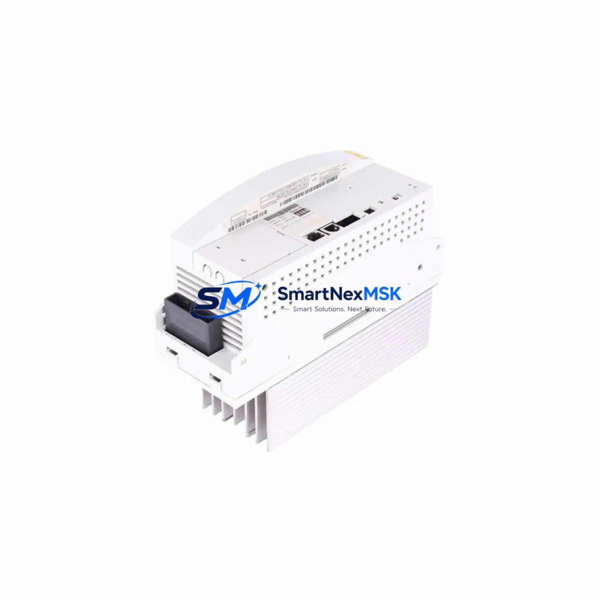
KUKA 00-252-423ZH-150180210F Retrofit-Ready AC Servo Motor for KR Series Control Systems
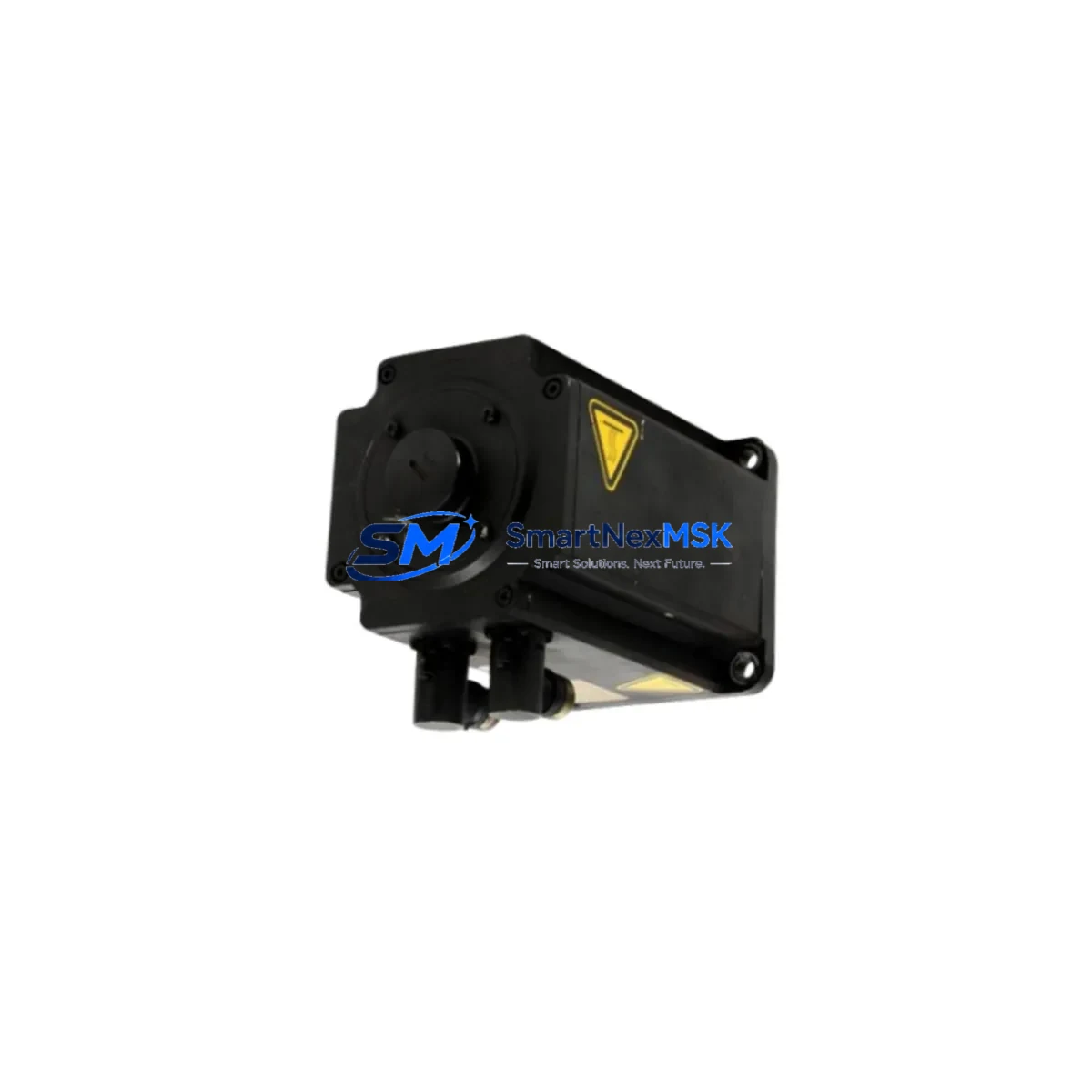
The KUKA 00-252-423ZH-150180210F is a precision AC servo motor engineered for seamless integration into KR Series robotic and industrial automation systems. As legacy KUKA servo drives and motion controllers reach end-of-life, plant engineers and system integrators increasingly rely on verified retrofit-ready replacements to sustain production continuity without committing to full system overhauls. This unit is sourced, inspected, and dispatch-tested to meet OEM mechanical and electrical specifications, making it a dependable choice for both emergency replacement and planned modernization projects.
Whether you are upgrading a KR 6, KR 16, KR 30, or KR 60 articulated arm, or maintaining a legacy KRC2 or KRC4 controller cabinet, the 00-252-423ZH-150180210F slots into the existing axis drive chain with minimal re-engineering. The motor’s encoder interface is compatible with the KUKA Resolver and EnDat feedback protocols used across the KR Series platform, eliminating the need for signal converter modules in most retrofit scenarios.
Upgrade Compatibility Table
| Parameter | Details |
|---|---|
| SKU / Part Number | 00-252-423ZH-150180210F |
| Brand | KUKA |
| Compatible Series | KR 6, KR 16, KR 30, KR 60, KR 120, KR 210 |
| Controller Compatibility | KRC2, KRC4, KRC4 compact |
| Feedback Interface | Resolver / EnDat 2.1 compatible |
| Mounting Standard | IEC 72-1 flange, direct axis-mount |
| Power Connector | M23 circular, 6-pin power + 12-pin encoder |
| Communication Protocol | KUKA proprietary servo bus (KSB), EtherCAT-ready variants |
| Replacement Recommendation | Direct drop-in for OEM-installed units; verify axis number and gear ratio |
| Commissioning Note | DSE mastering required after replacement; use KUKA smartPAD or WorkVisual |
| Warranty | 12 Months from dispatch date |
Retrofit Planning for Existing Automation Systems
A successful retrofit of the 00-252-423ZH-150180210F begins well before the motor arrives on site. Engineers should audit the existing KRC2 or KRC4 controller cabinet to confirm that the KPP (KUKA Power Pack) and KSP (KUKA Servo Pack) drive modules are rated for the replacement motor’s continuous and peak current draw. In many aging installations, the KSP 600-3×64 or KSP 600-3×20 servo amplifier modules may themselves be approaching service limits, and a concurrent inspection is advisable to avoid a secondary failure shortly after the motor swap.
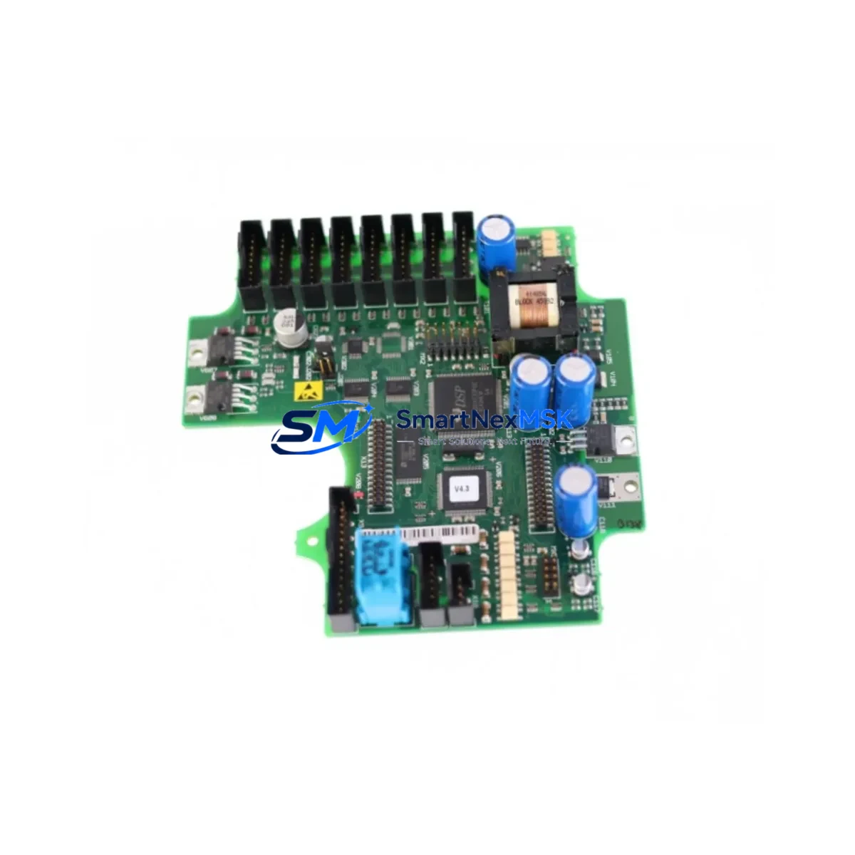
Terminal wiring at the motor junction box should be documented before disconnection. The M23 power connector pinout on the 00-252-423ZH-150180210F follows the standard KUKA color-code convention (U/V/W phases plus PE), but field technicians should verify against the axis-specific wiring diagram in the KR Series electrical documentation, particularly on machines that have undergone previous third-party repairs. The encoder cable — typically routed through the robot’s internal cable harness alongside the RDC (Robot Drive Computer) board — must be inspected for insulation fatigue, especially at the wrist and elbow articulation points where flex cycles accumulate.
For installations where the original motor has been in service for more than 80,000 operating hours, it is prudent to simultaneously replace the associated gear unit oil seals and check the backlash on the harmonic drive or planetary gearbox attached to the affected axis. The KUKA KR C4 system log, accessible via WorkVisual or the smartPAD diagnostic interface, will record cumulative axis load data that can guide this assessment.
When the control system includes a KUKA KR C4 with PROFINET or DeviceNet communication cards, the servo replacement does not require fieldbus reconfiguration, as motor identity is managed at the drive level through the RDC board’s axis parameterization file. However, if the installation uses an older KRC2 with a KUKA VxWorks-based controller, the axis machine data file (MADA) must be verified to ensure the motor type code matches the replacement unit. Mismatched MADA entries are a common source of commissioning errors and can trigger E-Stop faults during the initial power-on sequence.
I/O expansion modules such as the KUKA KIO (KUKA I/O) or third-party Beckhoff EtherCAT I/O terminals integrated into the control cabinet should remain unaffected by the motor swap, provided the cabinet power distribution — typically fed through a KUKA KPC (KUKA Power Cabinet) or equivalent 3-phase supply — is stable during the replacement window. Safety-rated I/O channels connected to the axis brake circuit must be re-validated after the motor is installed, in accordance with the site’s functional safety assessment.
HMI screens configured in KUKA WorkVisual or displayed on the smartPAD operator panel do not require modification for a like-for-like motor replacement. However, if the retrofit is part of a broader upgrade from KRC2 to KRC4, the HMI project will need to be migrated and re-commissioned, and any custom KRL (KUKA Robot Language) programs should be validated in simulation before live execution. The KUKA.Sim or OfficeLite virtual controller environment is recommended for pre-commissioning program verification.
Downtime Control During System Migration
Minimizing unplanned downtime is the primary operational concern when replacing a servo motor on a production robot. A structured approach begins with pre-staging: the 00-252-423ZH-150180210F should be bench-tested and its encoder verified before the maintenance window opens. Use a KUKA-compatible servo tester or the KRC4’s built-in drive diagnostics to confirm encoder signal integrity and motor insulation resistance (typically >100 MΩ at 500 VDC megger test).
The replacement sequence should follow the KUKA axis replacement procedure: power down the KRC4 or KRC2 controller, discharge the KPP DC bus capacitors (allow minimum 5 minutes after power-off), release the axis brake manually using the brake release board if the robot is not in a gravity-neutral position, and then proceed with motor removal. Retain the original axis mastering reference marks on the mechanical stop or use a dial gauge to record the pre-removal joint position — this data is essential for restoring DSE (Digital Servo Electronics) mastering after installation.
Once the 00-252-423ZH-150180210F is installed and all connectors are secured, perform a cold-start of the controller and navigate to the axis mastering menu on the smartPAD. Re-master the affected axis using the EMT (Electronic Mastering Tool) or the reference notch method, then execute a slow-speed test run across the full axis range before returning the robot to automatic mode. Log the new mastering values in the site’s maintenance record and back up the updated machine data to an external storage device via WorkVisual.
For multi-robot cells where a single axis failure can halt an entire line, maintaining a spare 00-252-423ZH-150180210F in the site’s critical spares inventory is a cost-effective strategy. Paired with a spare RDC board and a set of KSP servo amplifier modules, this inventory profile covers the most statistically frequent failure modes in a mature KR Series installation and can reduce mean time to repair (MTTR) from days to hours.
Retrofit Support FAQ
Q1: Is the 00-252-423ZH-150180210F a direct replacement for the original KUKA motor on my KR 16 axis 1?
A: In most KR 16 configurations, yes — the 00-252-423ZH-150180210F is a verified replacement for the axis 1 servo motor. You should confirm the gear ratio and brake voltage (24 VDC standard) against your robot’s type plate and the axis-specific MADA file before installation. If your KR 16 is a special variant (e.g., KR 16 arc HW or KR 16-2), contact our technical team with the robot serial number for confirmation.
Q2: What commissioning steps are required after installing this motor?
A: After mechanical installation and connector re-engagement, you must perform DSE mastering on the affected axis using the KUKA smartPAD EMT procedure. A slow-speed axis range test should follow, and the updated mastering data must be saved and backed up via WorkVisual. No fieldbus reconfiguration is required for like-for-like replacements on KRC4 systems.
Q3: Will my existing KRL programs run without modification after the motor swap?
A: Yes, for a like-for-like replacement on the same controller generation (KRC4 to KRC4 or KRC2 to KRC2). KRL programs reference axis coordinates and tool/base frames, not motor hardware directly. Re-mastering restores the kinematic reference, so existing programs will execute correctly after the mastering procedure is completed and verified.
Q4: What does the 12-month warranty cover?
A: The 12-month warranty covers manufacturing defects, encoder failure, winding insulation breakdown, and bearing failure under normal operating conditions. It does not cover damage resulting from incorrect installation, overvoltage events, or operation outside the motor’s rated duty cycle. All units are dispatch-tested for encoder signal quality and winding resistance before shipment. Warranty claims are processed within 5 business days of receipt of the returned unit.
—
© 2026 SMARTNEXMSK. All rights reserved.
Original Source: https://smartnexmsk.com
Contact: sales@smartnexmsk.com | +86 18259474341