KUKA 033.56.84.10C Retrofit-Ready Precision Reducer: Compatible Upgrade for Legacy Robot Control Systems
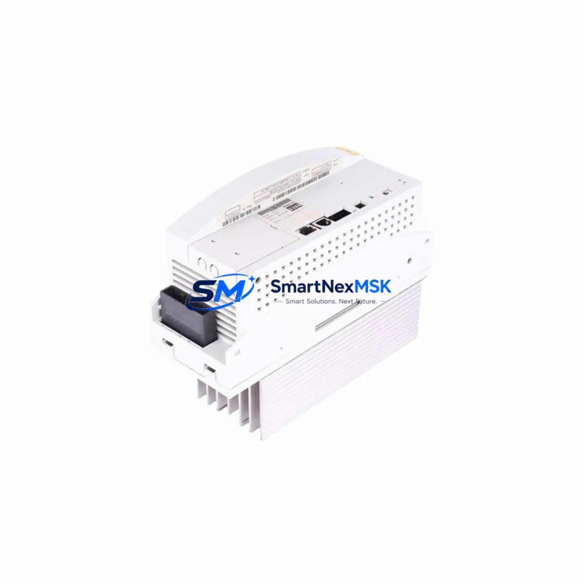
The KUKA 033.56.84.10C is a high-precision axis gearbox reducer engineered for KUKA industrial robot platforms. As automation lines age and OEM support for legacy configurations becomes limited, this precision reducer serves as a verified retrofit-ready replacement for facilities managing KUKA KR series robots, including KR 6, KR 16, KR 30, and KR 60 variants. Whether you are executing a planned maintenance overhaul, responding to an unplanned axis failure, or upgrading an aging robot cell to extend its operational lifespan, the 033.56.84.10C delivers the dimensional accuracy, torque rating, and backlash specification required for seamless mechanical integration.
This unit is also cross-referenced against the CLOOS 033.56.84.10D, making it a viable replacement candidate in welding robot applications where CLOOS and KUKA platforms share common drivetrain architectures. Engineers sourcing replacement gearboxes for CLOOS QIROX or ROMAT series welding robots should verify flange dimensions and output shaft tolerances before installation.
Upgrade Compatibility Table
| Parameter | Details |
|---|---|
| Part Number | 033.56.84.10C |
| Cross-Reference SKU | CLOOS 033.56.84.10D |
| Brand / Manufacturer | KUKA (Origin: Germany) |
| Component Type | Precision Axis Gearbox Reducer |
| Compatible Robot Series | KUKA KR 6, KR 16, KR 30, KR 60; CLOOS QIROX / ROMAT |
| Mounting Interface | Standard KUKA flange pattern; verify axis position (A1–A6) |
| Communication Compatibility | Mechanical only; integrates with KRC2, KRC4 controller platforms |
| Installation Requirement | Torque re-calibration via KUKA WorkVisual or smartPAD required post-swap |
| Retrofit Recommendation | Direct replacement; confirm axis load rating and grease specification |
| Commissioning Note | Zero-point mastering (EMT or dial gauge) mandatory after installation |
| Warranty | 12 Months from date of shipment |
Retrofit Planning for Existing Automation Systems
Replacing a precision reducer in an operational robot cell requires careful pre-planning to avoid extended downtime and configuration drift. Before removing the failed or worn 033.56.84.10C, engineers should document the current axis mastering data stored in the KRC4 or KRC2 controller. This data, accessible through KUKA WorkVisual, defines the zero-point reference for each axis and must be restored or re-established after the mechanical swap.
In a typical KUKA robot retrofit scenario, the gearbox replacement is one component within a broader system restoration workflow. The robot’s power supply module — often a KPS 600 or KPS 1500 within the KRC4 cabinet — must be verified for output stability before energizing the axis after reassembly. Voltage fluctuations during the commissioning phase can trigger drive faults on the KSP servo drives, which manage torque delivery to each axis motor. Inspecting the KSP 600 or KSP 300 servo drive units for fault history prior to the reducer swap is recommended practice.
The axis motor connected to the 033.56.84.10C gearbox — typically a KUKA brushless AC servo motor in the 1FK or 1FT series — should be inspected for bearing wear and encoder integrity during the same maintenance window. Replacing the gearbox while leaving a marginal motor in service risks a repeat failure within a short interval. The motor resolver or encoder signal is read by the RDC (Resolver Digital Converter) board inside the controller, and any signal anomaly will prevent successful mastering.
For facilities running multi-robot cells, the KUKA KR C4 controller’s KUKA System Bus (KSB) or PROFINET interface connects the robot to the broader PLC network — often a Siemens S7-300 or S7-1500 series controller managing cell sequencing. During the gearbox replacement window, the PLC program should be placed in a safe hold state, and the robot’s safety interface signals — including the external emergency stop circuit and the safety PLC handshake — should be verified before returning the robot to automatic mode.
Facilities using KUKA.SafeOperation or KUKA.SafeRangeMonitoring should re-validate the configured Cartesian and axis-specific safe zones after mastering, as a mastering offset can cause the robot to breach a monitored boundary during the first test cycle. The KUKA smartPAD teach pendant is the primary interface for this validation step and for running the initial slow-speed test program before resuming production speed.
If the retrofit involves upgrading from an older KRC2-based robot to a KRC4 platform, additional considerations apply: the KRC2 uses a different cabinet layout, a DSE-IBS (Digital Signal Electronics) board for I/O management, and a VxWorks-based real-time OS, while the KRC4 uses a Windows-based architecture with a separate safety controller. Program migration between these platforms requires use of the KUKA OfficeLite simulation environment and careful re-mapping of I/O addresses and motion parameters.
Downtime Control During System Migration
Minimizing unplanned downtime during a precision reducer replacement begins with pre-staging all required components before the maintenance window opens. In addition to the 033.56.84.10C gearbox itself, a complete swap kit should include the correct gearbox grease (KUKA Microlube GL 261 or equivalent per axis specification), new sealing elements, the appropriate torque wrench settings per the KUKA axis assembly manual, and a calibrated mastering tool — either the KUKA Electronic Mastering Tool (EMT) or a precision dial gauge fixture.
The robot program stored in the KRC controller should be backed up to an external USB drive or network share before any mechanical work begins. KUKA WorkVisual provides a full project archive function that captures the robot program, I/O configuration, safety parameters, and axis mastering data in a single exportable file. This archive is the fastest path to system recovery if a configuration error occurs during commissioning.
For cells where the robot is integrated with a vision system — such as a KUKA.VisionTech or third-party 2D/3D camera system — the tool center point (TCP) calibration should be re-verified after mastering, as even a small mastering offset will shift the TCP and cause pick-and-place or welding path errors. TCP re-calibration using the 4-point or XYZ method on the smartPAD typically adds 30–60 minutes to the commissioning process but is essential for path accuracy.
Where production schedules are tight, a pre-tested spare robot or a pre-assembled axis module can be swapped in as a unit, with the failed gearbox repaired offline. This hot-swap approach, combined with a pre-loaded WorkVisual project archive, can reduce total cell downtime to under two hours for experienced maintenance teams.
Retrofit Support FAQ
Q1: Is the KUKA 033.56.84.10C a direct drop-in replacement for the 033.56.84.10D used in CLOOS robots?
The 033.56.84.10C and the CLOOS-referenced 033.56.84.10D share a common design lineage and are frequently cross-referenced in multi-brand robot maintenance environments. However, engineers should verify flange bolt pattern, output shaft diameter, and gearbox housing dimensions against the specific axis assembly drawing before installation. Dimensional confirmation is always recommended when substituting across brand designations.
Q2: What commissioning steps are required after installing the 033.56.84.10C?
After mechanical installation and torque verification, the axis must be re-mastered using the KUKA EMT or a dial gauge at the mastering notch. The mastering data is entered via the KUKA smartPAD under the Mastering menu. Following mastering, a slow-speed test run of the robot program should be executed to verify path accuracy before returning to production speed. If KUKA.SafeOperation is active, safe zone validation is also required.
Q3: How do I verify wiring and signal integrity after the gearbox swap?
The motor cable and resolver/encoder cable connections at the axis motor should be inspected and re-seated during the gearbox replacement. The RDC board in the KRC controller monitors resolver signal quality; any cable damage or connector corrosion will generate an axis error on startup. Use the KUKA WorkVisual diagnostics or the smartPAD error log to identify resolver signal faults before attempting mastering.
Q4: What does the 12-month warranty cover?
The 12-month warranty covers manufacturing defects in materials and workmanship from the date of shipment. It does not cover damage resulting from improper installation, incorrect lubrication, operation outside rated load parameters, or physical impact. All units are function-tested prior to shipment. Warranty claims are processed through sales@smartnexmsk.com with proof of purchase and a fault description.
© 2026 SMARTNEXMSK. All rights reserved.
Original Source: https://smartnexmsk.com
Contact: sales@smartnexmsk.com | +86 18259474341