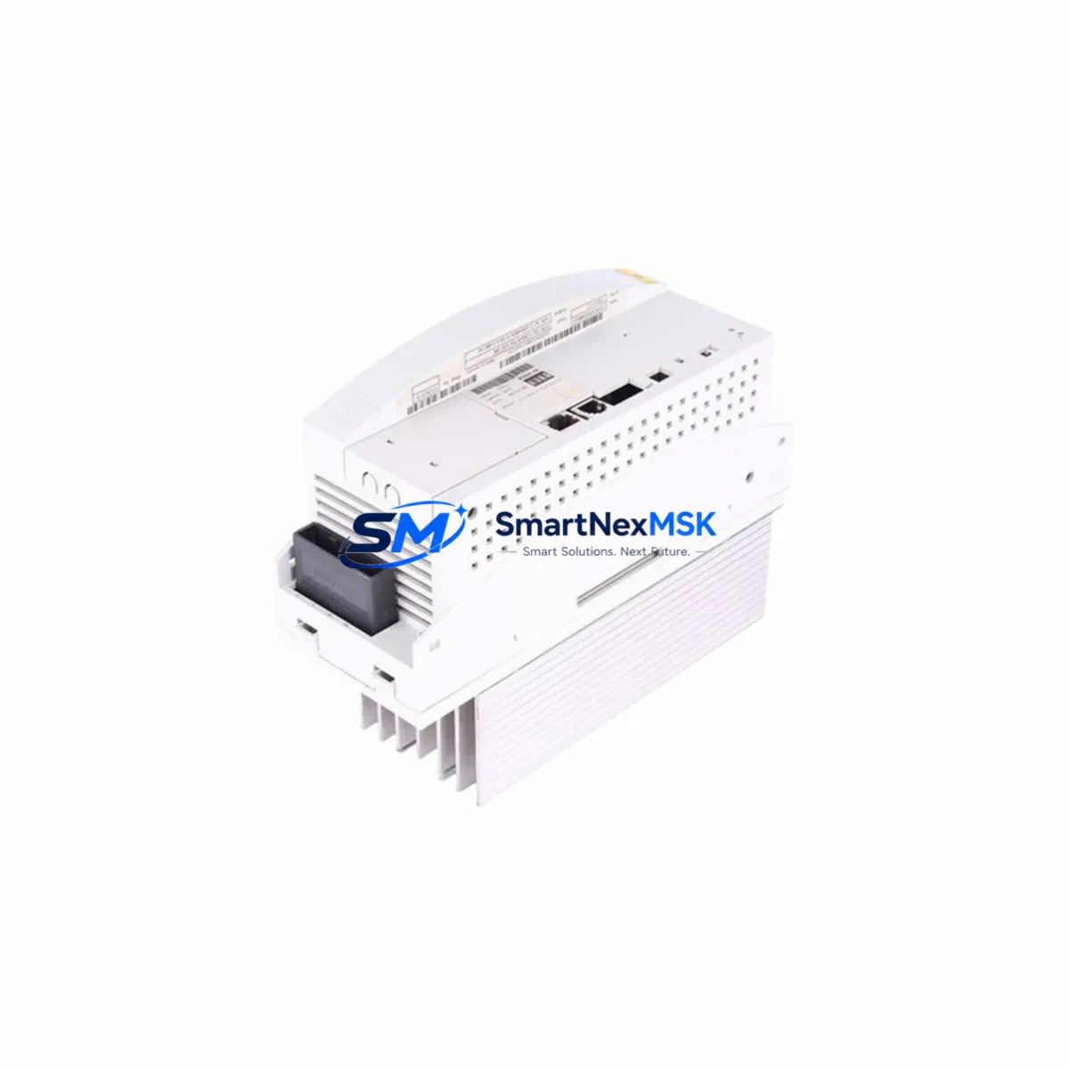
KUKA K202 00-017-361 Retrofit-Ready Interface for KRC2 Control Systems
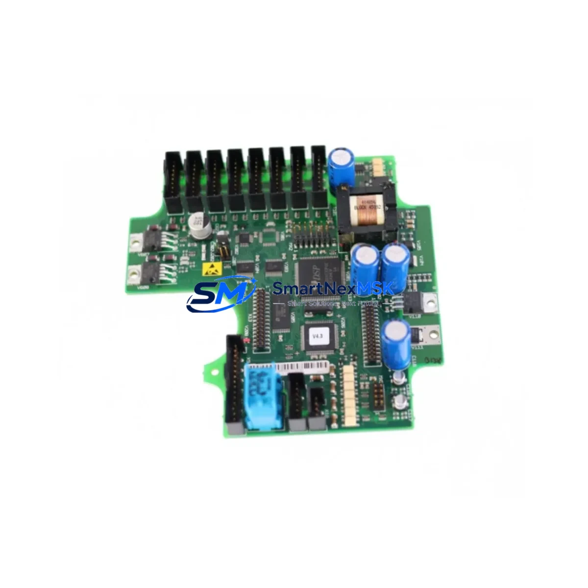
The KUKA K202 00-017-361 is a critical electronic interface board engineered for the KRC2 robot controller platform — one of the most widely deployed industrial robot control systems in automotive, metal fabrication, and general manufacturing environments. As KUKA progressively transitions its installed base toward the KRC4 and KRC5 architectures, the K202 00-017-361 remains an essential retrofit and replacement component for facilities that continue to operate KRC2-based workcells. This board serves as a direct replacement for discontinued part numbers including 00-273-150, 00-154-293, and 00-119-763, making it the preferred sourcing solution for maintenance engineers managing aging robot fleets.
Whether you are executing a planned control cabinet upgrade, responding to an unplanned board failure, or conducting a systematic modernization of a multi-robot production line, the K202 00-017-361 provides a verified, drop-in compatible solution that minimizes engineering risk and reduces total downtime exposure. Each unit shipped by SMARTNEXMSK is subject to pre-shipment functional testing and is backed by a 12-month warranty.
Upgrade Compatibility Table
| Parameter | Details |
|---|---|
| Primary SKU | K202 00-017-361 |
| Compatible Replacements | 00-273-150 / 00-154-293 / 00-119-763 |
| Target Controller Platform | KUKA KRC2 (all sub-variants) |
| Interface / Backplane Connector | KRC2 standard backplane slot; verify slot address before installation |
| Communication Compatibility | DeviceNet, PROFIBUS-DP (subject to KRC2 firmware version) |
| Power Supply Requirement | 24 VDC via KRC2 internal PSU; confirm PSU capacity before retrofit |
| Installation Requirement | ESD precautions; controller powered down; module address configured via DIP switch |
| Replacement Recommendation | Direct swap for listed discontinued part numbers; no firmware modification required in most KRC2 configurations |
| Commissioning Focus | Verify I/O mapping in WorkVisual or KRL program; confirm HMI signal assignments post-swap |
| Warranty | 12 months from date of shipment |
Retrofit Planning for Existing Automation Systems
A successful KRC2 retrofit begins well before the replacement board arrives on-site. Maintenance teams should start by auditing the existing control cabinet layout, documenting the current wiring harness routing, and confirming that the KRC2 power supply unit (PSU) — typically a 24 VDC regulated supply — has sufficient residual capacity to support the replacement interface board without derating. In multi-robot cells where several KRC2 controllers share a common power distribution panel, this step is especially important.
Next, engineers should capture a full backup of the robot program using KUKA WorkVisual or the onboard KCP teach pendant before any hardware is disturbed. This backup should include the complete KRL source, I/O configuration tables, safety configuration, and any bus topology definitions. If the cell uses a KUKA KPS 600 servo power supply or a KPP 600 power pack, verify that these units are not flagged with fault codes that could mask an underlying interface board issue — replacing the K202 00-017-361 without clearing upstream faults will not restore normal operation.
Terminal wiring on the K202 00-017-361 follows the KRC2 standard connector pinout. Before disconnecting the existing board, photograph or document all terminal assignments, particularly for external safety circuits, customer I/O, and fieldbus connections. If the cell communicates over PROFIBUS-DP using a KUKA PROFIBUS CP communication module, confirm that the DP address settings on the replacement board match the original configuration — mismatched addresses will cause the PLC master (commonly a Siemens S7-300 or S7-400 series controller) to report a station failure immediately upon restart.
For cells that have already migrated part of their I/O infrastructure to EtherNet/IP or PROFINET via an external gateway, the K202 00-017-361 retrofit is typically transparent to the network layer, provided the gateway’s IP address and device name remain unchanged. However, if the retrofit is part of a broader migration toward a KUKA KRC4 controller, engineers should plan for a parallel commissioning phase where both the legacy KRC2 and the new KRC4 cabinet are powered simultaneously, allowing HMI screen layouts and safety interlock logic to be validated before the old controller is decommissioned.
Rack and backplane integrity should also be inspected during the retrofit. The KUKA KRC2 backplane connector pins are susceptible to oxidation in high-humidity environments; cleaning with isopropyl alcohol and verifying positive seating of the replacement module is a standard commissioning step. If the existing rack shows signs of physical damage or corrosion, sourcing a replacement KRC2 mounting rack assembly concurrently with the K202 00-017-361 is advisable to avoid a secondary failure shortly after the initial repair.
Finally, if the robot cell uses a KUKA MFC3 motion control board or a DSE-IBS safety board in the same cabinet, confirm that these modules are seated correctly and show no fault LEDs after the K202 00-017-361 is installed and the controller is powered up. A KUKA programming cable (KCP cable) connected to a laptop running WorkVisual is the recommended tool for final I/O verification and program upload confirmation.
Downtime Control During System Migration
Unplanned downtime during a KRC2 interface board failure is one of the highest-cost events in a robot-dependent production environment. The K202 00-017-361 is stocked for immediate dispatch precisely to address this scenario. When a board failure is confirmed, the recommended response sequence is: (1) isolate the affected robot and place the cell in a safe hold state without shutting down adjacent robots on the same line; (2) retrieve the pre-saved WorkVisual project backup from a network share or USB archive; (3) install the replacement K202 00-017-361 following ESD-safe procedures; (4) power up the KRC2 controller and allow the boot sequence to complete before connecting the KCP teach pendant; (5) perform a cold start and verify that all I/O signals, safety inputs, and fieldbus communications are restored to their pre-failure state.
For facilities with a documented spare-parts strategy, maintaining one K202 00-017-361 as a hot-spare in the control room significantly reduces mean time to repair (MTTR). The board’s compact form factor and standard KRC2 backplane interface mean that a trained technician can complete the physical swap in under 30 minutes, with full program restoration and production restart achievable within two hours in most configurations. This approach preserves the original KRL program logic, maintains all safety interlock definitions, and avoids the need for a full re-teach of robot positions — protecting both production continuity and process quality.
Retrofit Support FAQ
Q1: Is the K202 00-017-361 a direct replacement for 00-273-150 and 00-154-293?
Yes. The K202 00-017-361 is the current active part number that supersedes 00-273-150, 00-154-293, and 00-119-763 in KRC2 controller applications. No firmware modification is required in standard KRC2 configurations. Confirm the backplane slot address via DIP switch settings on the original board before installation.
Q2: What commissioning steps are required after installing the replacement board?
After physical installation, power up the KRC2 controller and perform a cold start. Use WorkVisual or the KCP teach pendant to verify that all I/O assignments, fieldbus addresses, and safety configurations are intact. If any signals are missing, reload the pre-saved project backup and re-download to the controller. Confirm HMI screen signal bindings if an external operator panel is in use.
Q3: How is terminal wiring compatibility verified before installation?
Document all existing terminal assignments from the original K202 board before removal. The K202 00-017-361 uses the standard KRC2 connector pinout, so wiring is directly compatible. Pay particular attention to external safety circuit connections (E-stop chains, safety gate inputs) and fieldbus cable routing to avoid signal inversion or open-circuit faults after reconnection.
Q4: What does the 12-month warranty cover, and how is it claimed?
The 12-month warranty covers manufacturing defects and functional failures under normal operating conditions from the date of shipment. Each unit undergoes pre-shipment functional testing. To initiate a warranty claim, contact SMARTNEXMSK with the original order reference, a description of the fault symptom, and photographic evidence of the installation. Replacement or repair will be arranged within the warranty period at no additional cost.
© 2026 SMARTNEXMSK. All rights reserved.
Original Source: https://smartnexmsk.com
Contact: sales@smartnexmsk.com | +86 18259474341