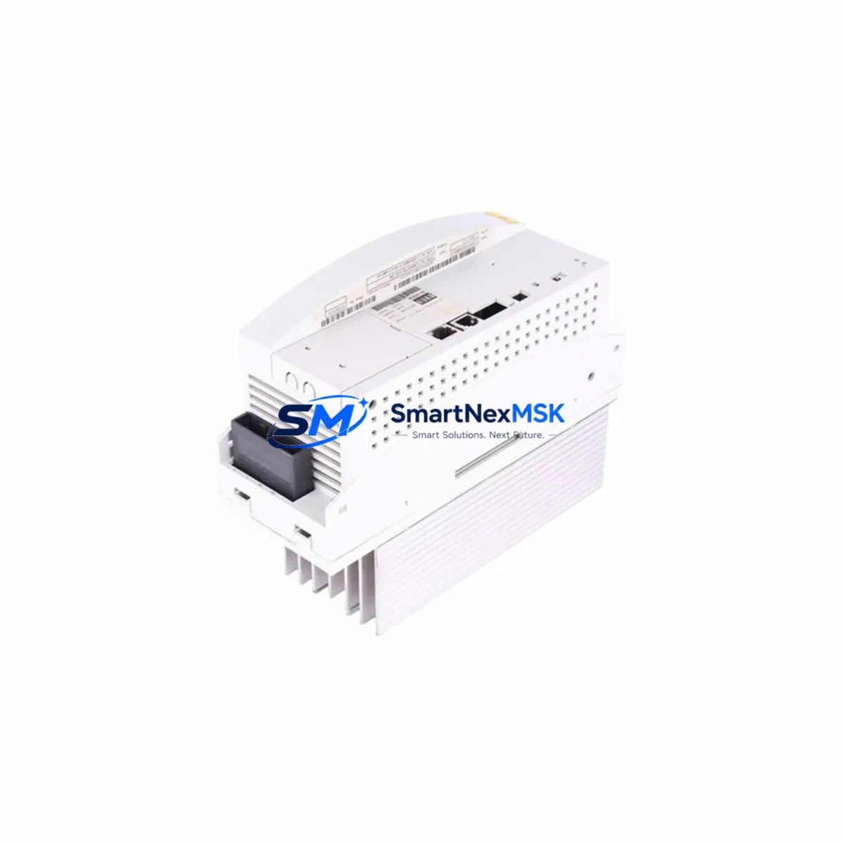
KUKA KPP600-20-1X40 Retrofit-Ready Servo Drive for KPP600 Control Systems
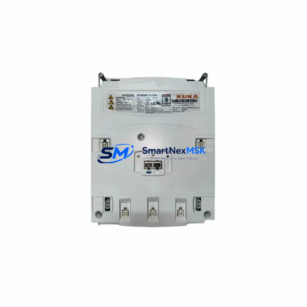
The KUKA KPP600-20-1X40 (Part No. 00-198-260) is a high-performance servo drive module engineered for seamless integration into KUKA KPP600-series robot control cabinets. As original KUKA KPP600 units approach end-of-life and spare parts become increasingly scarce, this retrofit-ready replacement provides a verified drop-in solution for system integrators, maintenance engineers, and automation managers responsible for keeping production lines operational.
Whether you are replacing a failed unit in a KR C2 or KR C4 controller cabinet, upgrading an aging servo axis, or restoring a decommissioned robot cell to full production capacity, the KPP600-20-1X40 delivers the electrical and mechanical compatibility required for a controlled, low-risk migration. The module is pre-tested prior to shipment, covered by a 12-month warranty, and supported by our technical team throughout the commissioning process.
Upgrade Compatibility Table
| Parameter | KPP600-20-1X40 (00-198-260) | Notes |
|---|---|---|
| Compatible Series | KUKA KPP600 Series | KR C2 / KR C4 cabinet platforms |
| Replaces | KPP600-20-1X20, KPP600-20-1X32 (discontinued) | Verify axis count and power rating before swap |
| Backplane Interface | KUKA KPP600 standard backplane connector | Confirm slot position and address jumper settings |
| Communication Protocol | KUKA proprietary KLI / EtherCAT-compatible | Verify KSS software version compatibility |
| Power Supply Requirement | DC bus from KPS600 or KPS1500 power supply | Confirm bus voltage and current capacity |
| Terminal Wiring | Standard KPP600 motor power and resolver connectors | Re-use existing cable harness where possible |
| Installation Format | Rack-mount, KPP600 slot-compatible | No mechanical modification required |
| Commissioning Tool | KUKA WorkVisual / KSS Teach Pendant | Axis mastering required after replacement |
| Warranty | 12 Months | Covers manufacturing defects; pre-shipment tested |
Retrofit Planning for Existing Automation Systems
A successful KPP600-20-1X40 retrofit begins well before the replacement unit arrives on site. Engineers should start by auditing the existing control cabinet to confirm the KPS600 or KPS1500 power supply module is delivering adequate DC bus voltage and current headroom for the replacement axis. In multi-axis cabinets, the combined load of all active KPP600 servo drive slots must remain within the power supply’s rated output — a calculation that is especially critical when upgrading from a lower-rated predecessor module.
Terminal wiring should be documented before any module is removed. The motor power connector and resolver feedback cable routed from the robot arm to the drive slot must be labeled and photographed. In older KR C2 installations, the RDC (Resolver-to-Digital Converter) board mounted inside the robot base may also require inspection, as resolver signal integrity directly affects axis calibration after the new drive is seated.
For cabinets running KUKA System Software (KSS) versions 5.x through 8.x, the module address configuration — typically set via DIP switches or backplane slot assignment — must match the axis number defined in the robot’s machine data. Mismatched addressing is one of the most common causes of post-replacement faults. Engineers should export and archive the current machine data file from the KR C4 controller or legacy KR C2 before powering down, ensuring a restore point is available if commissioning reveals parameter conflicts.
In systems where the KUKA KCP2 teach pendant or a third-party HMI panel is used for operator interaction, screen layouts and axis-specific alarm messages tied to the replaced drive should be reviewed. If the plant uses a PROFIBUS DP or EtherNet/IP gateway module within the cabinet for PLC integration, communication link continuity must be verified after the swap — particularly if the drive replacement changes the cabinet’s internal EtherCAT node count.
I/O expansion modules such as the KUKA KIO digital I/O boards or third-party Beckhoff EtherCAT terminals integrated into the same control rack should be left powered where safe to do so during the drive swap, minimizing the scope of the restart sequence. Where a full cabinet power-down is unavoidable, a pre-agreed restart checklist covering all field devices — including safety relays, external axis encoders, and conveyor interlocks — will reduce unplanned delays.
Downtime Control During System Migration
Minimizing production downtime during a KPP600-20-1X40 replacement requires a structured approach to pre-staging, execution, and verification. The replacement module should be received, inspected, and bench-verified against the original unit’s part number and firmware label before the maintenance window opens. Our pre-shipment testing protocol confirms that each unit powers up correctly and passes basic drive self-diagnostics, reducing the risk of a second unplanned outage caused by a defective replacement part.
During the maintenance window, the recommended sequence is: archive the current robot program and machine data backup to an external USB or network share; power down the cabinet following the KUKA-prescribed E-Stop and main disconnect procedure; remove the failed KPP600 module; seat the KPP600-20-1X40 in the same backplane slot; reconnect all motor power and resolver cables; restore power; and perform axis mastering using the KSS teach pendant. In most KR C2 and KR C4 installations, this sequence can be completed within two to four hours by a qualified KUKA service engineer or trained maintenance technician.
Where the robot is part of a synchronized production cell — for example, coordinated with a KUKA KR AGILUS or KR QUANTEC arm on a shared conveyor — the cell controller or upstream PLC should be placed in a safe hold state before the cabinet is opened. This protects both personnel and the integrity of the original ladder logic or structured text program running on the line PLC, which should not require modification as a result of the drive replacement alone.
After commissioning, a short production trial run under supervised conditions — typically 30 to 60 minutes of normal cycle operation — is recommended before returning the cell to full autonomous production. Any residual axis position errors or torque limit warnings observed during this trial should be logged and addressed before sign-off.
Retrofit Support FAQ
Q1: Is the KPP600-20-1X40 (00-198-260) a direct drop-in replacement for earlier KPP600 variants?
In most KR C2 and KR C4 cabinet configurations, yes. The KPP600-20-1X40 shares the same backplane form factor and connector pinout as earlier KPP600-20 variants. However, engineers should verify the axis power rating (1×40 A) matches the motor requirements of the axis being replaced, and confirm that the KSS software version installed on the controller supports the module’s firmware revision.
Q2: What wiring changes are required during installation?
In standard retrofit scenarios, no wiring changes are required. The existing motor power cable and resolver feedback harness connect directly to the KPP600-20-1X40 using the original connectors. If the cabinet has been modified or the original cables are damaged, our technical team can advise on compatible replacement cable assemblies and connector specifications.
Q3: Does the replacement unit require re-mastering or re-programming of the robot?
Axis mastering is required after any servo drive replacement, as the absolute position reference stored in the drive is reset. The robot program itself does not need to be rewritten — the existing KRL (KUKA Robot Language) programs and machine data remain valid. Mastering is performed using the KSS teach pendant and typically takes 15 to 30 minutes per axis.
Q4: What does the 12-month warranty cover, and how is it claimed?
The 12-month warranty covers manufacturing defects and component failures under normal operating conditions. Each unit undergoes pre-shipment functional testing before dispatch. In the event of a warranty claim, contact our support team with the order reference and a description of the fault. We will arrange a replacement or repair at no additional cost within the warranty period.
© 2026 SMARTNEXMSK. All rights reserved.
Original Source: https://smartnexmsk.com
Contact: sales@smartnexmsk.com | +86 18259474341