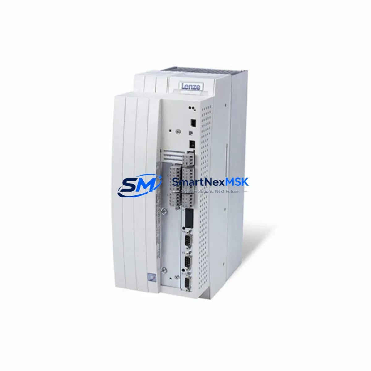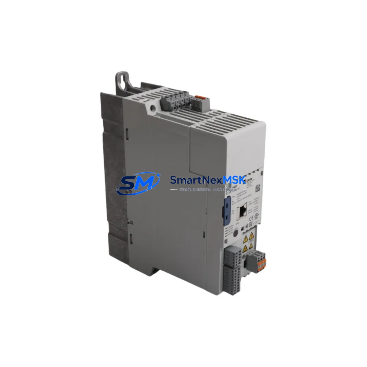
Lenze E84AVSCE7514SX0 Retrofit-Ready AC Drive for 8400 StateLine Control Systems
The Lenze E84AVSCE7514SX0 is a 7.5 kW AC variable frequency drive from the Lenze 8400 StateLine series, purpose-built for retrofit and modernization projects in industrial automation environments. Whether you are replacing an end-of-life drive on a legacy production line, upgrading a control cabinet to meet current safety standards, or migrating from an older Lenze 8200 vector or 8400 motec platform, this unit delivers a reliable, specification-matched solution with minimal re-engineering effort.
Designed for three-phase 400 V AC supply networks, the E84AVSCE7514SX0 supports both CANopen and PROFIBUS DP communication protocols, making it directly compatible with existing fieldbus architectures without requiring gateway hardware or protocol converters. Its compact footprint and standard DIN-rail or panel-mount installation profile allow direct substitution into existing control cabinet layouts, preserving original wiring harness routing and terminal block assignments wherever possible.
Upgrade Compatibility Table
| Parameter | Detail |
|---|---|
| SKU / Part Number | E84AVSCE7514SX0 |
| Series | Lenze 8400 StateLine |
| Power Rating | 7.5 kW (10 HP) |
| Supply Voltage | 3-phase 380–480 V AC, 50/60 Hz |
| Output Current | 18.5 A nominal |
| Communication Protocols | CANopen (CiA 402), PROFIBUS DP |
| Installation Type | Panel mount / control cabinet |
| Cooling Method | Forced air (integrated fan) |
| Common Replacement Targets | Lenze 8200 vector, 8400 motec, E84AVSCE5514SX0 |
| Terminal Compatibility | Standard Lenze X1/X2/X3 terminal layout retained |
| Commissioning Tool | Lenze Engineer software, GDC keypad |
| Debugging Interface | PC via USB-to-RS232 programming cable or GDC operator panel |
| Warranty | 12 months from date of shipment |
Retrofit Planning for Existing Automation Systems
Successful integration of the E84AVSCE7514SX0 into a running production environment requires a structured pre-installation audit. Begin by documenting the existing drive’s parameter set using the Lenze GDC operator panel or Lenze Engineer software connected via a USB-to-RS232 programming cable. Export all parameter groups — including ramp times, motor nameplate data, PID setpoints, and fieldbus node addresses — before powering down the old unit.
On the power supply side, verify that the upstream Lenze power supply module or mains filter (such as the EMC filter E82ZZ751 2B) can sustain the inrush current demand of the replacement drive during startup. Check the DC bus capacitor bank condition if the cabinet uses a shared DC bus topology with adjacent drives such as the Lenze E84AVSCE5514SX0 (5.5 kW) or E84AVSCE1114SX0 (11 kW) units operating in multi-axis configurations.
Terminal block reassignment is typically straightforward: the X1 mains input terminals, X2 motor output terminals, and X3 control signal terminals follow the same physical layout as predecessor 8400 StateLine variants. However, if migrating from an 8200 vector series drive, the control terminal pinout differs — particularly for the digital input (DI) and analog input (AI) assignments. Prepare a revised wiring diagram before disconnecting any signal cables, and label each conductor individually to prevent mis-termination during reinstallation.
For systems using Lenze I/O extension modules (such as the EPM-S100 or EPM-S200 series) connected via the system bus, confirm that the module address settings and baud rate configuration are preserved. The E84AVSCE7514SX0 retains full compatibility with these I/O expanders when operating on CANopen, allowing existing I/O mapping tables in the PLC program to remain unchanged.
If the control system uses a Lenze L-force Controller or a third-party PLC (Siemens S7-300, S7-1200, or Mitsubishi Q-series) communicating over PROFIBUS DP, re-import the GSD file for the 8400 StateLine series into the network configuration tool (STEP 7, TIA Portal, or GX Works) and verify that the DP slave address matches the original node assignment. No changes to the PLC program logic or HMI screen tag bindings should be required if the fieldbus address is preserved.
HMI panels connected to the drive — whether a Lenze XT HMI or a third-party panel via Modbus RTU — should be tested in simulation mode before live commissioning. Confirm that all drive status tags (run/fault/speed feedback) resolve correctly against the new unit’s register map. Where the HMI project references drive-specific parameter codes, cross-check against the E84AVSCE7514SX0 parameter list to identify any code offsets introduced between firmware generations.
Backplane and rack considerations apply if the drive is installed in a Lenze modular system cabinet alongside a Lenze 8400 TopLine or 8400 HighLine controller module. Confirm that the shared DC bus connector (if used) and the system bus ribbon cable are seated correctly and that the cabinet’s total power dissipation budget accommodates the replacement unit’s thermal output.
Downtime Control During System Migration
Minimizing production downtime during a drive replacement requires pre-staging the replacement unit with a cloned parameter set before the maintenance window begins. Using Lenze Engineer software, upload the full parameter backup from the outgoing drive to a laptop, then download it to the E84AVSCE7514SX0 on the bench. Perform a no-load motor test (motor disconnected, output terminals open) to confirm that the drive powers up without fault codes and that the fieldbus communication link is established correctly.
During the physical swap, retain all original cable labels and photograph the terminal block layout before disconnection. Reinstall the replacement drive, reconnect all terminals in sequence (PE ground first, then mains, then motor, then control signals), and restore the fieldbus cable last. Power up the cabinet in a controlled sequence: mains contactor first, then enable the drive via the PLC run command, and monitor the first few acceleration ramps for any overcurrent or ground fault indications.
If the original program logic uses a Lenze ECS servo controller or motion controller in a coordinated axis group, isolate the replaced axis from the motion coordinator during initial commissioning and run it in local speed control mode first. This protects the original program logic and prevents unintended axis interactions while the replacement drive is being verified. Once speed and torque response are confirmed, re-integrate the axis into the coordinated motion group and perform a full cycle test before returning the line to production.
All units supplied by SMARTNEXMSK are pre-tested under load conditions prior to shipment and include a 12-month warranty covering manufacturing defects and functional failures. Inventory is maintained in-stock for fast dispatch, with typical lead times of 3–7 business days for international destinations.
Retrofit Support FAQ
Q1: Is the E84AVSCE7514SX0 a direct drop-in replacement for the Lenze 8200 vector series?
The E84AVSCE7514SX0 is functionally compatible in terms of power rating and motor control capability, but the 8200 vector series uses a different control terminal layout (X3 pinout) and a different parameter structure. A wiring adapter or terminal re-mapping is required, and the parameter set must be re-entered manually rather than transferred directly. We recommend consulting the Lenze 8200-to-8400 migration guide and verifying all DI/DO assignments before commissioning.
Q2: Can I transfer parameters directly from the old drive to the E84AVSCE7514SX0?
Yes, if the outgoing unit is also from the 8400 StateLine series (same firmware generation). Use Lenze Engineer software to export the parameter file (.par) from the old drive and import it into the replacement unit. If the firmware versions differ by more than one major revision, review the parameter change log in the Lenze release notes and manually adjust any deprecated or renamed parameters before the first run.
Q3: What commissioning steps are required after installation?
After physical installation and parameter restore, perform the following: (1) verify supply voltage at X1 terminals is within 380–480 V AC ±10%; (2) confirm motor nameplate data (rated voltage, current, frequency, speed) matches the drive parameter set; (3) run the motor identification routine (if motor data was not previously stored); (4) test all digital inputs and outputs via the drive’s I/O monitor function; (5) verify fieldbus communication by checking the DP/CANopen status LED and confirming cyclic data exchange with the PLC. Document all commissioning results for the maintenance record.
Q4: What does the 12-month warranty cover, and what is the return process?
The 12-month warranty covers all manufacturing defects and functional failures under normal operating conditions. It does not cover damage caused by incorrect wiring, overvoltage events, environmental contamination, or unauthorized modification. To initiate a warranty claim, contact SMARTNEXMSK with the order reference, a description of the fault symptom, and any fault codes displayed. We will arrange return shipping and provide a replacement or repaired unit within the agreed service lead time.
© 2026 SMARTNEXMSK. All rights reserved.
Original Source: https://smartnexmsk.com
Contact: sales@smartnexmsk.com | +86 18259474341