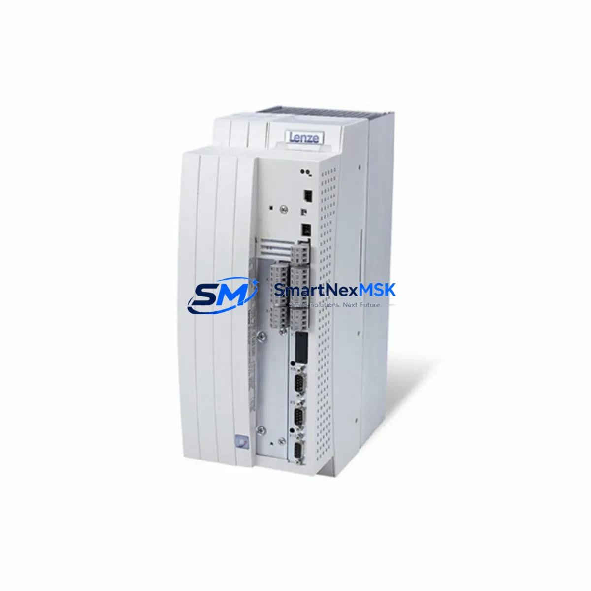
LENZE EVF9331-EV Spare for EVF 9300 Series Automation: Precision Replacement for Industrial Downtime Control
The LENZE EVF9331-EV is a critical AC servo inverter drive within the EVF 9300 series — one of LENZE’s most widely deployed variable frequency drive platforms across European and Asian manufacturing facilities. When this unit fails or reaches end-of-service life, every minute of unplanned downtime translates directly into production loss. Sourcing a verified, original-specification replacement is not simply a procurement task — it is a maintenance engineering decision that determines how quickly your line returns to full operation.
At SMARTNEXMSK, we supply the EVF9331-EV as a maintenance-ready spare: tested before dispatch, packaged for safe transit, and backed by a 12-month warranty. Whether you are a maintenance engineer executing an emergency swap or a procurement engineer building a strategic spare parts inventory, this unit is available for immediate quotation and fast worldwide shipping.
Spare Maintenance Table
| Parameter | Specification / Value |
|---|---|
| SKU / Part Number | EVF9331-EV |
| Brand | LENZE |
| Series | EVF 9300 (Servo Inverter Drive Series) |
| Product Type | AC Servo Inverter Drive / Variable Frequency Drive (VFD) |
| Drive Topology | PWM-controlled AC vector drive |
| Input Voltage | 3-phase 380–480 V AC (±10%), 50/60 Hz |
| Output Frequency Range | 0–650 Hz (application dependent) |
| Control Mode | V/f control, sensorless vector, closed-loop vector (encoder feedback) |
| Communication Interface | LECOM-A/B (RS-232/RS-485); optional PROFIBUS-DP, CANopen, DeviceNet modules |
| Protection Class | IP20 (cabinet-mount); suitable for control panel installation |
| Cooling Method | Forced air cooling (integrated fan) |
| Operating Temperature | 0°C to +40°C (derating above 40°C) |
| Storage Temperature | -25°C to +55°C |
| Humidity | ≤95% RH, non-condensing |
| Origin | Germany (DE) |
| Compatibility | Direct replacement for EVF 9300 series; compatible with LENZE 9300 servo PLC and E82 series system architectures |
| Installation | DIN rail or panel mount; standard LENZE wiring topology |
| Warranty | 12 Months — covers manufacturing defects, functional failure under normal operating conditions |
| Pre-shipment Testing | Power-on functional test, parameter initialization verification |
| Shipping | Worldwide; EMS / DHL / FedEx; anti-static and shock-resistant packaging |
Maintenance Planning for Continuous Operation
Replacing the EVF9331-EV in a live production environment is rarely an isolated task. Experienced maintenance engineers know that a drive failure is often a symptom of broader stress within the electrical cabinet. Before commissioning the replacement unit, a thorough inspection of the surrounding components is essential to prevent repeat failures and ensure system stability.
Begin with the input power supply: verify that the upstream 3-phase supply voltage is within the rated tolerance of 380–480 V AC. A degraded or unbalanced supply is a leading cause of premature drive failure. Check the input line reactor or EMC filter — LENZE recommends dedicated line filters for the EVF 9300 series to suppress conducted emissions and protect the drive’s rectifier stage. If the existing filter shows signs of overheating or insulation breakdown, replace it alongside the drive.
Inspect the DC bus capacitors and braking resistor circuit. In applications with frequent deceleration cycles — such as conveyor systems or winding machines — the braking resistor and its associated chopper circuit absorb significant energy. A failed or undersized braking resistor can cause DC bus overvoltage faults that damage the replacement drive within hours of installation. Verify the resistance value and thermal rating before powering up.
On the motor side, check the output cable insulation resistance using a megohmmeter before connecting the new drive. Degraded motor winding insulation or damaged output cables can cause immediate overcurrent trips. If the system uses an output sine filter or dV/dt filter, inspect it for capacitor degradation — these components protect the motor windings from high-frequency switching stress and should be part of any planned maintenance cycle.
Review the I/O wiring and terminal block connections (X1, X3, X5 on standard EVF 9300 configurations). Loose or corroded terminals on analog reference inputs (0–10 V or 4–20 mA speed reference signals) and digital control inputs (enable, fault reset, direction) are a common source of intermittent faults that are misdiagnosed as drive failures. Clean and re-torque all terminal connections during the replacement procedure.
If the system uses LENZE communication modules — such as the E82ZAFPC (PROFIBUS-DP) or E82ZAFCC (CANopen) fieldbus adapters — verify that the module firmware and node address settings are correctly transferred to the replacement drive. A mismatch in PROFIBUS GSD configuration or CANopen PDO mapping will prevent the PLC from recognizing the new drive, causing a system-level fault even though the drive itself is functioning correctly.
For systems integrated with a LENZE 9300 Servo PLC or connected to a Siemens S7-300/S7-400 PLC via PROFIBUS, confirm that the drive parameters are backed up using LENZE’s Global Drive Control (GDC) software or the keypad parameter set before removing the old unit. Parameter sets should be stored in the maintenance documentation and updated after every replacement. If the system includes a LENZE HMI panel (such as the XT series or a third-party Weintek/Siemens TP panel), verify that the drive address and communication timeout settings are consistent with the replacement unit’s configuration.
Finally, check the control cabinet thermal management: clean or replace cabinet cooling filters, verify fan operation, and confirm that the drive’s minimum clearance distances (top, bottom, and sides) are maintained. Thermal stress from inadequate ventilation is a primary driver of capacitor aging and IGBT degradation in frequency inverters.
Site Replacement Workflow
Step 1 — Documentation and Parameter Backup: Before de-energizing the system, record all drive parameters using GDC software or the keypad upload function. Photograph the terminal wiring layout. Note the firmware version displayed on the keypad or GDC interface.
Step 2 — Safe Isolation: Isolate the drive from the mains supply using the upstream isolator or circuit breaker. Wait a minimum of 5 minutes for the DC bus capacitors to discharge before opening the cabinet. Verify zero voltage on the DC bus terminals using a calibrated multimeter.
Step 3 — Mechanical Removal: Disconnect all power cables (L1/L2/L3 input, U/V/W motor output, PE ground), control wiring (X1, X3, X5 terminal blocks), and any fieldbus communication cables. Remove the drive from its mounting position — DIN rail clip or panel mounting screws as applicable.
Step 4 — Inspection of Adjacent Components: With the drive removed, inspect the mounting surface, cable routing, and adjacent components as described in the maintenance planning section above. Address any identified issues before installing the replacement.
Step 5 — Installation of EVF9331-EV Replacement: Mount the new unit, reconnect all wiring in the documented sequence, and verify terminal torque values per LENZE specifications. Restore the parameter set from backup using GDC or keypad download.
Step 6 — Commissioning and Functional Test: Apply power and verify that the drive initializes without fault codes. Run the motor at low speed (5–10 Hz) in both directions to confirm correct rotation and control response. Gradually increase to full operating speed and verify current, voltage, and temperature readings are within normal range. Confirm PLC communication status (PROFIBUS/CANopen data exchange active).
Step 7 — Documentation Update: Record the replacement date, new unit serial number, and parameter set version in the maintenance log. Update the spare parts inventory to trigger reorder of a replacement EVF9331-EV for future use.
Spare Parts Support FAQ
Q1: Is the EVF9331-EV a direct drop-in replacement for other EVF 9300 series models?
The EVF9331-EV is a specific power rating and feature variant within the EVF 9300 series. While the mechanical form factor and wiring topology are consistent across the series, power ratings, current output, and optional communication modules vary by model number. Always verify the full SKU — including suffix codes (e.g., -EV, -ER, -ES) — against the original nameplate before ordering. SMARTNEXMSK’s technical team can assist with cross-reference verification prior to shipment.
Q2: What pre-shipment testing is performed on the EVF9331-EV before dispatch?
Every unit supplied by SMARTNEXMSK undergoes a power-on functional test to verify that the drive initializes correctly, displays no fault codes, and responds to basic control inputs. Parameter factory defaults are confirmed, and the unit is inspected for physical damage before packaging. Units are shipped in anti-static, shock-resistant packaging with a test record included in the shipment documentation.
Q3: What does the 12-month warranty cover, and how is a warranty claim processed?
The 12-month warranty covers manufacturing defects and functional failures under normal operating conditions as specified in the LENZE EVF 9300 technical documentation. It does not cover damage resulting from incorrect installation, overvoltage events, environmental contamination, or unauthorized modification. To initiate a warranty claim, contact SMARTNEXMSK with the original invoice number, a description of the fault, and any available fault code history. Our team will arrange return logistics and provide a replacement or repair within an agreed timeframe.
Q4: How should the EVF9331-EV be stored as a long-term spare?
For long-term storage (6 months or more), the drive should be kept in its original anti-static packaging in a dry, temperature-controlled environment (0°C to +40°C, ≤75% RH, non-condensing). Avoid storage near strong magnetic fields or corrosive atmospheres. It is recommended to power up stored drives for a minimum of 30 minutes every 12 months to reform the DC bus electrolytic capacitors and prevent capacitance degradation. Record the storage power-up date in your maintenance log.
© 2026 SMARTNEXMSK. All rights reserved.
Original Source: https://smartnexmsk.com
Contact: sales@smartnexmsk.com | +86 18259474341