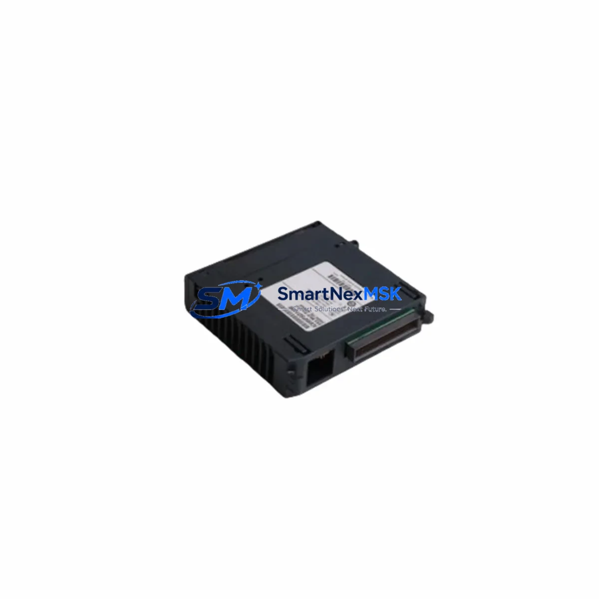
LENZE EPM-S501.2A.10 Retrofit-Ready Analog Output Module for ECS/EPM Control Systems
The LENZE EPM-S501.2A.10 is a high-precision analog output module engineered for seamless integration into LENZE ECS and EPM series servo drive and motion control platforms. As legacy ECS/EPM installations reach end-of-service milestones, this module serves as the definitive retrofit solution — enabling engineers to restore full analog signal output capability without redesigning the control cabinet or rewriting existing PLC programs. Whether you are replacing a failed unit, upgrading a discontinued component, or modernizing a multi-axis servo system, the EPM-S501.2A.10 delivers the electrical and mechanical compatibility required for a controlled, low-risk migration.
Sourced directly from authorized distribution channels and subject to full functional testing prior to dispatch, each unit ships with a 12-month warranty covering manufacturing defects and operational failures under normal industrial conditions. SMARTNEXMSK maintains verified stock of this module to support urgent breakdown recovery and planned maintenance windows across global industrial sites.
Upgrade Compatibility Table
| Parameter | Details |
|---|---|
| Compatible Series | LENZE ECS, EPM, 9300 Servo PLC, E94 series |
| Module Type | Analog Output Module |
| Signal Output | ±10 V / 0–20 mA (configurable per channel) |
| Backplane Interface | ECS/EPM standard module slot — direct plug-in, no adapter required |
| Terminal Wiring | Compatible with original EPM terminal block layout; no rewiring required for standard configurations |
| Communication Compatibility | CANopen, LECOM-A/B, PROFIBUS-DP (via host controller) |
| Replaces / Supersedes | EPM-S501.1A, EPM-S501.2A (earlier revisions) |
| Installation Requirement | Standard DIN rail or ECS rack slot mounting; no mechanical modification needed |
| Commissioning Note | Module address must be confirmed in LENZE Engineer or Global Drive Control software before power-on |
| Warranty | 12 months from date of shipment — covers manufacturing defects and functional failures |
Retrofit Planning for Existing Automation Systems
Successful integration of the EPM-S501.2A.10 into an existing LENZE ECS or EPM control platform begins with a thorough pre-retrofit audit. Engineers should first verify the available power budget on the ECS power supply module — typically an EPM-S100 or EPM-S110 series unit — to confirm that the additional analog output load falls within the rated output capacity of the backplane bus. Overloading the internal 24 VDC supply rail is a common cause of intermittent faults during post-retrofit commissioning.
Terminal block wiring should be mapped against the original EPM-S501 wiring diagram. In most ECS rack configurations, the analog output channels connect to a 10-pin or 15-pin terminal strip on the module front face. If the existing installation uses a LENZE EPM-T100 terminal expansion adapter, verify that the adapter revision is compatible with the .2A.10 hardware revision before proceeding. Mismatch between adapter and module revisions has been observed to cause channel offset errors in 0–20 mA output mode.
Module slot addressing is configured via rotary switch or software parameter depending on the ECS rack generation. For systems running LENZE 9300 Servo PLC firmware, the module address must be declared in the function block library before the analog output object is instantiated. Engineers migrating from an older EPM-S501.1A should export the existing parameter set using Global Drive Control (GDC) software and verify that all C-parameter assignments remain valid under the new hardware revision. In most cases, parameter sets are forward-compatible, but channel scaling factors (C0412–C0415 range) should be re-verified on the bench before live commissioning.
For systems that include a LENZE EMF2131IB or EMF2133IB PROFIBUS-DP communication module, the GSD file version should be checked against the current firmware of the host ECS controller. Communication link integrity between the analog output module and the upstream PROFIBUS master — often a Siemens S7-300 CPU or a Beckhoff CX series controller — must be validated using a bus diagnostic tool before the system is returned to production. Similarly, if the control cabinet includes a LENZE KP200 or KP500 operator panel for local HMI interaction, screen tag assignments linked to analog output setpoints should be reviewed and re-tested after module replacement.
I/O expansion scenarios involving the EPM-S501.2A.10 alongside LENZE EPM-S400 digital input modules or EPM-S410 digital output modules require careful slot sequencing within the ECS rack. The ECS backplane assigns logical I/O addresses based on physical slot position; inserting the analog output module into a different slot than the original unit will shift all downstream module addresses and may invalidate existing PLC program I/O mappings. Always document the original slot layout before removing any module from the rack.
Where the retrofit involves a full control cabinet upgrade — replacing an aging ECS rack with a current-generation LENZE i700 servo inverter platform — the EPM-S501.2A.10 can serve as a bridging component during the transition phase, maintaining analog output continuity on legacy machine axes while the new drive platform is commissioned in parallel. This staged approach is strongly recommended for multi-axis systems where simultaneous cutover of all axes would result in unacceptable production downtime.
Downtime Control During System Migration
Minimizing unplanned downtime during an EPM-S501.2A.10 replacement requires a structured pre-outage preparation protocol. Before the maintenance window opens, the complete ECS parameter set should be backed up using LENZE Engineer software and stored on a local engineering workstation as well as a removable medium. This backup captures all drive parameters, function block configurations, and analog output scaling data, ensuring that the system can be restored to its pre-fault state within minutes if the replacement module exhibits unexpected behavior during initial power-on.
The physical replacement procedure should be performed with the ECS rack de-energized and the 24 VDC logic supply isolated. After seating the new EPM-S501.2A.10 in the correct backplane slot, verify module address settings before restoring power. On first power-up, monitor the ECS diagnostic LED array and the status register of the analog output module via GDC to confirm that the module is recognized by the rack controller and that no address conflict or hardware fault code is generated.
For systems where the analog output channels drive critical process variables — such as speed reference signals to downstream frequency inverters or position setpoints to hydraulic servo valves — it is advisable to perform a channel-by-channel output verification using a calibrated milliamp meter or voltage reference before reconnecting field wiring. This step confirms that the replacement module’s output accuracy is within specification and prevents process upsets caused by calibration drift between hardware revisions.
Where the control system architecture permits, a hot-standby spare module pre-configured with the correct parameter set and address settings can be staged in the control cabinet, reducing the active replacement time to under 15 minutes. SMARTNEXMSK recommends maintaining at least one verified spare EPM-S501.2A.10 on-site for any production line where this module is a single point of failure. All units supplied by SMARTNEXMSK are pre-tested under load conditions and shipped with a test report confirming output accuracy across all channels.
Retrofit Support FAQ
Q1: Is the EPM-S501.2A.10 a direct drop-in replacement for the EPM-S501.1A?
In the majority of ECS and EPM rack installations, yes. The .2A.10 revision maintains the same backplane connector pinout, terminal block layout, and module slot footprint as the .1A revision. However, engineers should verify that the host ECS controller firmware version supports the .2A hardware revision — firmware versions below V3.x on certain 9300 Servo PLC platforms may require a parameter update before the new module is recognized correctly.
Q2: What commissioning steps are required after installing the replacement module?
After physical installation, confirm the module slot address via rotary switch or software, restore the parameter backup using Global Drive Control or LENZE Engineer, and perform a channel output verification with a reference instrument. For PROFIBUS-DP connected systems, re-initialize the bus and confirm that the analog output module appears correctly in the master’s I/O configuration. Full commissioning typically requires 30–90 minutes depending on system complexity.
Q3: Can the EPM-S501.2A.10 be used in a mixed rack alongside older EPM module revisions?
Yes. The ECS backplane is designed to support mixed-revision module populations. The EPM-S501.2A.10 can coexist in the same rack with EPM-S400 digital input modules, EPM-S410 digital output modules, EPM-S100 power supply modules, and earlier analog module revisions without electrical conflict. Logical address assignments are determined by slot position, not module revision, so no special configuration is required for mixed-revision racks.
Q4: What does the 12-month warranty cover, and how is a warranty claim processed?
The 12-month warranty covers all manufacturing defects and functional failures occurring under normal industrial operating conditions, including output channel failure, backplane communication errors, and hardware faults not caused by external overvoltage or physical damage. To initiate a warranty claim, contact SMARTNEXMSK with the original order reference and a description of the fault. Replacement units are dispatched within 3 business days of claim approval, and failed units are returned via prepaid shipping label for root-cause analysis.
© 2026 SMARTNEXMSK. All rights reserved.
Original Source: https://smartnexmsk.com
Contact: sales@smartnexmsk.com | +86 18259474341