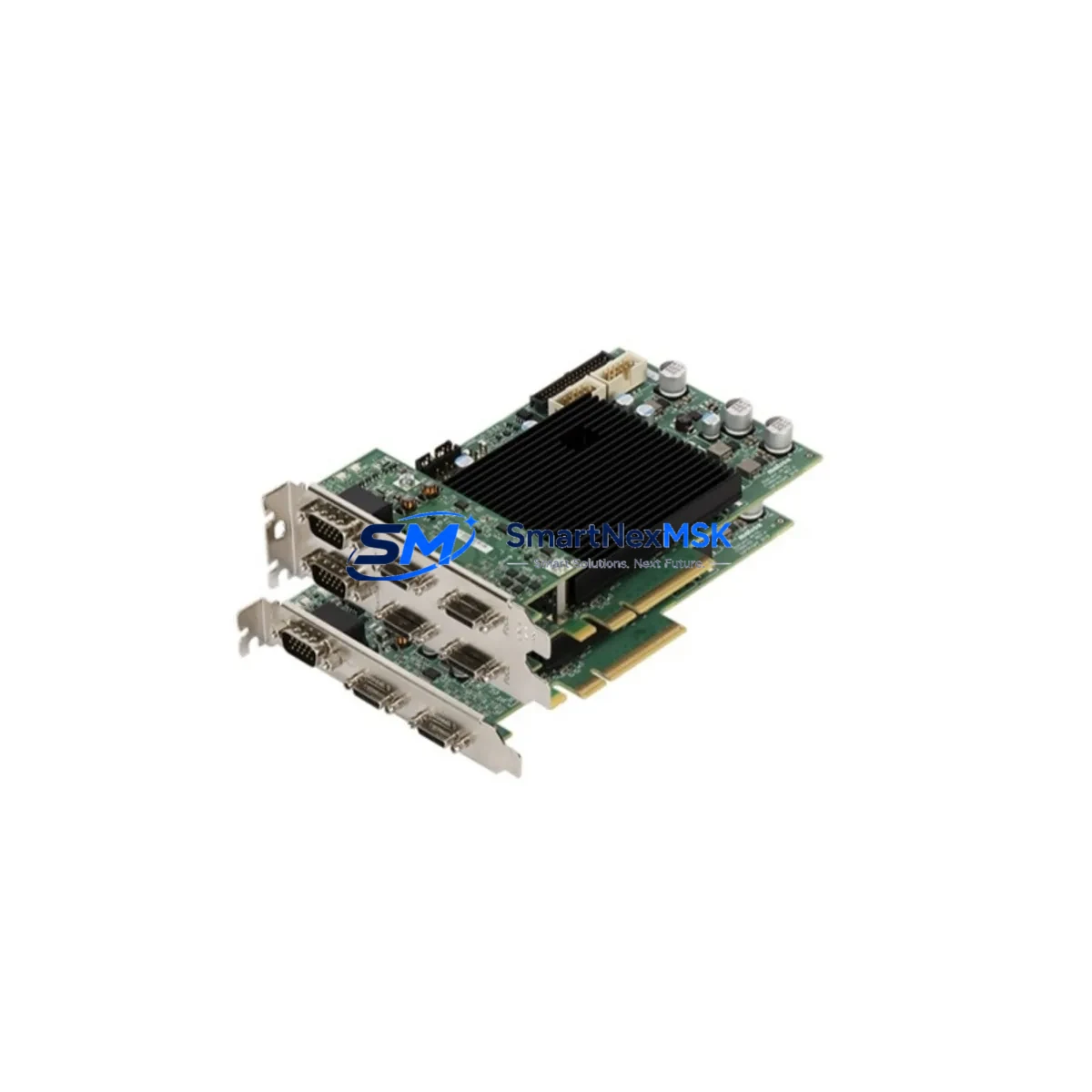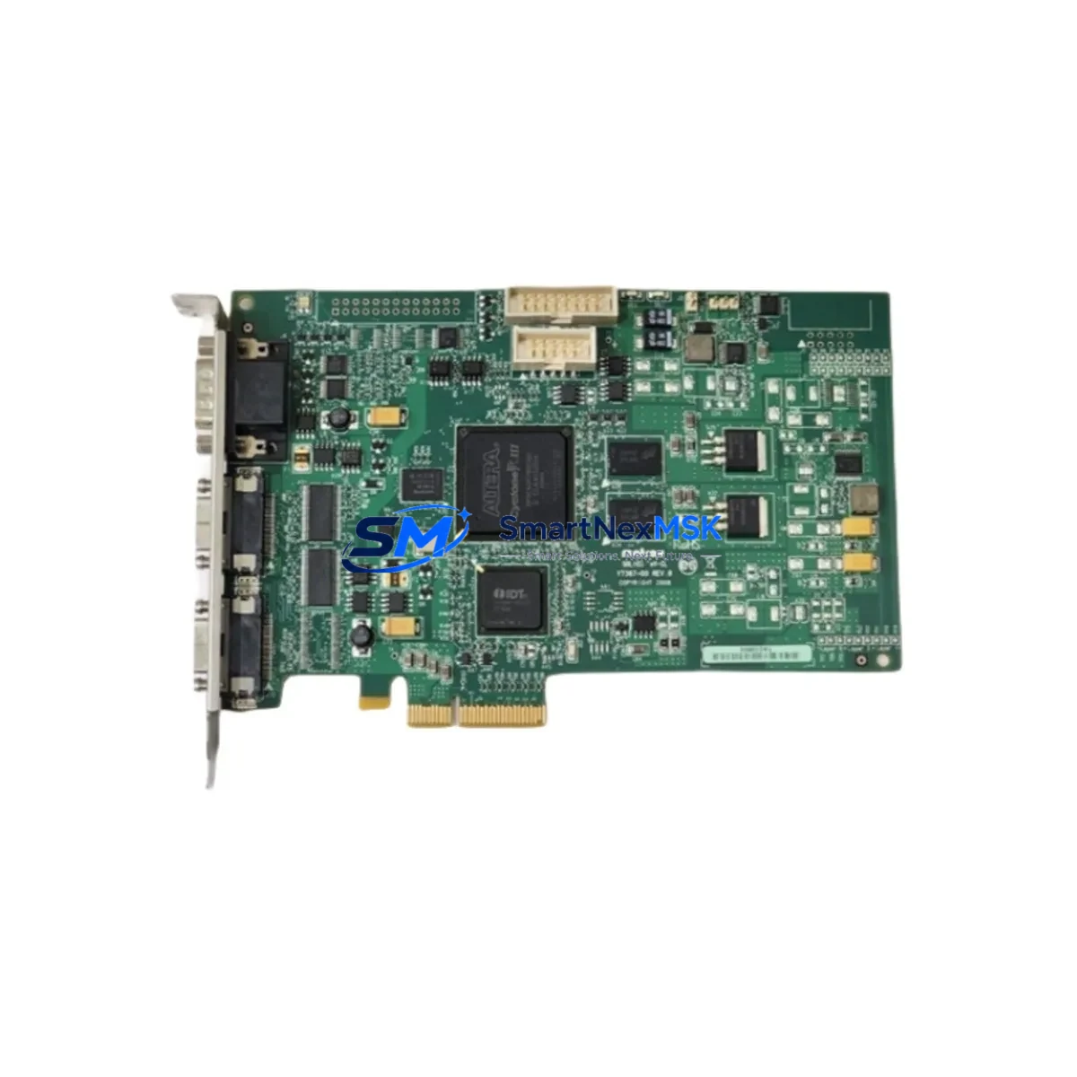
Matrox IP-8/AT/256 Retrofit-Ready Frame Capture for Imaging Series Control Systems
The Matrox IP-8/AT/256 is an ISA-bus frame capture and image processing board originally designed for integration into Matrox Imaging Series machine vision platforms. As production lines age and original equipment manufacturers discontinue ISA-based hardware, the demand for verified retrofit-ready replacements has grown significantly across industrial automation, quality inspection, and process control environments. This unit is sourced, tested, and supplied to support legacy system continuity, planned modernization projects, and emergency spare-part recovery — with a 12-month warranty covering all supplied units.
Whether your facility is operating a legacy inspection cell built around the Matrox Imaging Library (MIL), maintaining a vision-guided robotic assembly line, or managing a multi-camera quality control station that was commissioned in the 1990s or early 2000s, the IP-8/AT/256 remains a critical component. Its onboard 256 KB of image memory, AT-bus interface, and compatibility with Matrox’s proprietary image acquisition pipeline make it non-trivially replaceable without careful planning. We supply this board specifically to bridge the gap between discontinued OEM availability and your operational continuity requirements.
Upgrade Compatibility Table
| Parameter | Details |
|---|---|
| SKU | IP-8/AT/256 |
| Brand | Matrox |
| Series | Matrox Imaging Series |
| Bus Interface | ISA (AT-bus), 16-bit |
| Onboard Memory | 256 KB image buffer |
| Host Compatibility | IBM PC/AT and compatible ISA-slot industrial PCs |
| Software Compatibility | Matrox Imaging Library (MIL), Inspector, Genesis |
| Replacement Path | Direct drop-in for IP-8/AT/256; evaluate Matrox Meteor-II or Solios for PCI/PCIe migration |
| Communication Protocol | Parallel ISA data bus; RS-170 / CCIR analog video input |
| Installation Requirement | ISA slot in host PC; IRQ and DMA jumper configuration required |
| Debugging Focus | IRQ conflict resolution, DMA channel assignment, MIL driver version alignment |
| Warranty | 12 months from date of shipment |
| Origin | Canada (Matrox Electronic Systems Ltd.) |
| Condition | Refurbished / New Old Stock — function-tested prior to shipment |
Retrofit Planning for Existing Automation Systems
Integrating the IP-8/AT/256 into an existing or aging automation system requires a structured approach. The board occupies a full-length ISA slot, so the host industrial PC — often a rack-mounted IPC chassis from manufacturers such as Advantech or Siemens — must have a free 16-bit ISA slot available. Before installation, engineers should audit the current IRQ map to avoid conflicts with other ISA peripherals such as serial communication cards or legacy motion controller boards.
In systems where the IP-8/AT/256 interfaces with a Matrox Genesis or Matrox Inspector host application, the MIL runtime version must be confirmed. Mismatched driver versions between the board firmware and the MIL library can cause acquisition failures or frame drop errors. If the host PC is running a 16-bit DOS or early Windows NT environment, the original Matrox board support package (BSP) disk set is required for driver installation — we recommend confirming software availability before ordering hardware.
For facilities planning a phased migration rather than a full cutover, the IP-8/AT/256 can continue to serve as the primary frame capture device while a parallel PCI-based system — such as a Matrox Meteor-II/Standard or Matrox Orion — is commissioned on a secondary inspection station. This parallel-run approach allows operators to validate image quality, lighting calibration, and trigger timing on the new platform before decommissioning the ISA-based system. During this phase, the Matrox Camera Link or analog coaxial camera cabling, frame grabber trigger cables, and strobe controller wiring should all be documented and labeled for the transition.
In control cabinet environments, the IP-8/AT/256 host PC is often co-located with a PLC — such as a Siemens S5 or Allen-Bradley SLC 500 — that provides machine cycle triggers via a digital I/O interface card. The handshake between the PLC digital output and the frame grabber’s external trigger input must be verified for voltage compatibility (typically 5V TTL). If the PLC has been upgraded to a Siemens S7-300 or S7-400 series with a CP 343-1 Ethernet communication module, the trigger architecture may need to be redesigned to accommodate the new I/O response timing. Similarly, if the HMI has been migrated from a Siemens OP7 or OP17 panel to a modern TP700 Comfort or TP1200 Comfort touch panel, the vision result display screens will need to be redrawn in TIA Portal WinCC to reflect the new communication variables.
For I/O expansion in the same control cabinet, engineers frequently work alongside Siemens ET 200S distributed I/O modules or Wago 750-series fieldbus couplers to extend digital signals to remote inspection stations. The IP-8/AT/256 host PC communicates inspection pass/fail results to the PLC via these I/O modules, so any changes to the I/O module addressing or fieldbus topology — such as migrating from PROFIBUS DP to PROFINET — must be reflected in both the PLC program and the MIL-based vision application’s output logic. Rack and backplane changes, such as replacing a Siemens UR2 universal rack with a newer IM 153-2 interface module for distributed I/O, should also be accounted for in the retrofit plan.
Downtime Control During System Migration
Minimizing unplanned downtime during a frame grabber replacement or machine vision system upgrade is a primary concern for production managers. The recommended approach is to pre-stage the replacement IP-8/AT/256 board in a bench-test environment before the scheduled maintenance window. This includes installing the board in an identical or equivalent ISA-slot IPC, loading the correct MIL driver version, connecting a test camera, and verifying acquisition at the expected resolution and frame rate.
During the actual swap, the original program logic — including MIL application configuration files, camera calibration data, and inspection recipe parameters — should be backed up to a network share or USB drive before the board is removed. If the vision application stores calibration data in a hardware-specific format tied to the board’s serial number or memory map, this data must be re-validated after the replacement board is installed. In most MIL-based systems, the camera calibration and inspection thresholds are stored in software configuration files and are fully portable between boards of the same model.
For systems where the IP-8/AT/256 is part of a larger multi-board imaging array — for example, paired with a Matrox IP-8/AT/512 for extended memory or a Matrox IP-8/AT/DUAL for dual-channel acquisition — each board must be individually tested after installation to confirm that the multi-board synchronization and shared memory addressing remain intact. The total planned maintenance window for a single-board replacement in a well-documented system is typically two to four hours; for multi-board or multi-camera systems, allow six to eight hours and schedule the work during a planned production shutdown.
All units supplied by SMARTNEXMSK are function-tested prior to shipment. Test reports confirming acquisition functionality are available upon request. This pre-shipment testing significantly reduces the risk of receiving a non-functional board and helps compress the on-site maintenance window to the minimum required for physical installation and software validation.
Retrofit Support FAQ
Q: Is the IP-8/AT/256 a direct replacement for my existing board?
A: Yes, provided your host PC has a free 16-bit ISA slot and your system runs a compatible version of the Matrox Imaging Library (MIL). The IP-8/AT/256 is a like-for-like replacement in terms of bus interface, memory configuration, and software compatibility. If your system uses a different memory configuration — such as the IP-8/AT/512 — the board is not a direct drop-in and will require MIL configuration adjustments.
Q: What commissioning steps are required after installation?
A: After physical installation, you will need to configure the IRQ and DMA jumpers to match your system’s available resources, install or confirm the correct MIL board support package, connect your analog camera via the board’s BNC or LEMO input, and run a live acquisition test to verify frame capture at the expected resolution. If the board is replacing a failed unit in a production system, restore the backed-up MIL configuration files and re-run the inspection recipe validation before returning the line to production.
Q: Can I use this board if I am migrating from ISA to PCI?
A: The IP-8/AT/256 is an ISA-only board and cannot be installed in a PCI slot. If your migration plan involves moving to a PCI or PCIe platform, this board serves as a bridge solution to maintain production continuity on the existing ISA-based system while the new PCI-based frame grabber — such as a Matrox Meteor-II or Matrox Solios — is being commissioned in parallel. We can advise on migration sequencing upon request.
Q: What does the 12-month warranty cover?
A: The 12-month warranty covers manufacturing defects and functional failures under normal operating conditions. All boards are function-tested prior to shipment, and a test report is available upon request. The warranty does not cover damage resulting from incorrect installation, electrostatic discharge, or operation outside the board’s specified environmental parameters. Warranty claims are processed within five business days of receipt of the returned unit.
© 2026 SMARTNEXMSK. All rights reserved.
Original Source: https://smartnexmsk.com
Contact: sales@smartnexmsk.com | +86 18259474341