Mitsubishi A1SD71-S2 Retrofit-Ready Positioning Module: Compatible Modernization and Smooth MELSEC-A System Upgrade
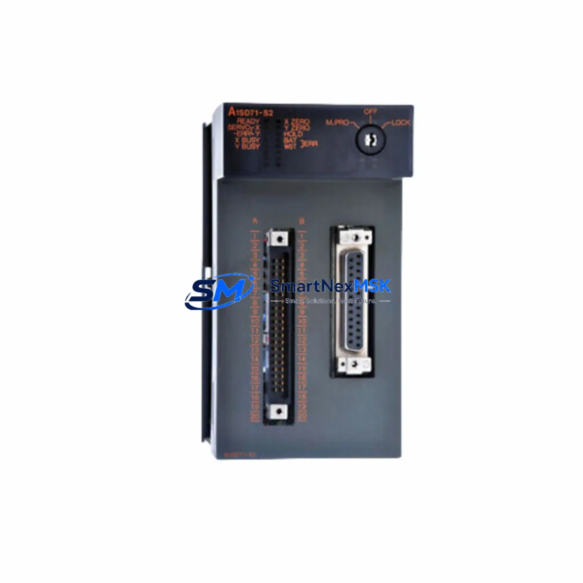
The Mitsubishi A1SD71-S2 is a single-axis positioning module originally designed for the MELSEC-A series programmable logic controller platform. As the MELSEC-A series has reached end-of-life and Mitsubishi Electric has officially discontinued production of A-series components, industrial facilities worldwide are facing the critical challenge of sourcing verified replacement units or executing a controlled migration to a supported platform. SMARTNEXMSK maintains in-stock inventory of the A1SD71-S2 to support both immediate spare-part replacement and phased retrofit projects, backed by a 12-month warranty and pre-shipment functional testing.
The A1SD71-S2 mounts directly into an A-series base unit such as the A1S38B or A1S52B rack, occupying a single slot and communicating with the CPU — typically an A1SCPU, A2SCPU, or A3NCPU — via the internal bus. It provides pulse-train output to servo amplifiers and stepper drivers, supporting both PTP (point-to-point) and speed-position switching control. Engineers replacing a failed unit must verify that the replacement module carries the correct hardware revision and that the existing GX Developer or SW0SRX-GPPA ladder program does not reference axis parameters that differ between sub-variants.
Upgrade Compatibility Table
| Parameter | A1SD71-S2 (This Unit) | Retrofit / Migration Notes |
|---|---|---|
| Control Axes | 1 axis | For 2-axis needs, pair with a second A1SD71-S2 or migrate to QD75D2 on Q-series |
| Rack Compatibility | A1S38B, A1S52B, A1S65B, A1S68B | Not compatible with Q-series or iQ-R racks; adapter base required for cross-series migration |
| CPU Interface | A-series internal bus | Direct drop-in for A1SCPU / A2SCPU / A3NCPU systems; verify I/O assignment in program |
| Output Type | Differential pulse output (CW/CCW or PULSE/SIGN) | Confirm servo amplifier input mode matches; MR-J2S and MR-J3 series are commonly paired |
| Communication Protocol | A-bus (proprietary backplane) | No CC-Link or MELSECNET support on this module; add A1SJ71UC24-R4 for serial comms if needed |
| Programming Tool | GX Developer / SW0SRX-GPPA | GX Works2 can read A-series projects in compatibility mode; verify positioning data blocks |
| Installation | DIN-rail mounted base unit, single slot | Confirm slot address matches existing FROM/TO instructions in ladder logic |
| Warranty | 12-Month Warranty — all units tested before shipment | |
Retrofit Planning for Existing Automation Systems
A successful A1SD71-S2 replacement begins well before the module arrives on-site. The first step is a full audit of the control cabinet: confirm the A1S power supply module (such as the A1S61PN or A1S62PN) can deliver sufficient current for the replacement module alongside all other installed I/O — the A-series backplane distributes 5 VDC internally, and an overloaded power supply is a common cause of intermittent faults after a module swap. Document the terminal wiring on the existing A1SD71-S2’s 20-pin connector, paying particular attention to the pulse output lines (FP, RP, COM), the ready signal (RDY), and the zero-point return input (DOG). These signals must be re-terminated identically on the replacement unit.
Next, record the module’s slot address within the base unit. The A1SD71-S2 occupies a specific slot number that is referenced by FROM and TO instructions in the GX Developer ladder program. If the replacement module is installed in a different slot — even temporarily during testing — the CPU will address the wrong device and positioning commands will not execute. Where the original rack is an A1S38B with mixed I/O, the slot map typically includes digital input modules such as the A1SX40 or A1SX80, digital output modules such as the A1SY10 or A1SY40P, and possibly an analog module like the A1S68AD for process feedback. All of these must remain in their original positions during the swap to avoid re-addressing the entire program.
For facilities that are using this replacement as the trigger for a broader platform migration — moving from MELSEC-A to MELSEC-Q or iQ-R — the positioning function can be replicated using the QD75D1 or QD75D2 on a Q-series rack such as the Q38B, with the CPU upgraded to a Q06UDEHCPU or similar. In this scenario, the servo amplifier wiring remains largely unchanged if the site uses MR-J2S or MR-J3 drives, but the positioning program must be re-created in GX Works2 using the QD75 positioning data format, which differs structurally from the A1SD71-S2’s parameter tables. HMI screens built on GOT1000 or GOT2000 panels will also require screen updates to reflect the new device addresses, particularly any speed override or current position display elements.
If the system includes a CC-Link network managed by an A1SJ61BT11 master module, the migration plan must account for re-mapping all remote I/O station addresses. Similarly, any MELSECNET/10 links using an A1SJ71LP21 or A1SJ71BR11 network module will need to be re-evaluated, as Q-series uses MELSECNET/H with different station configuration tools. SMARTNEXMSK can supply all of these associated modules from stock to support a complete, single-source retrofit bill of materials.
Downtime Control During System Migration
Minimizing unplanned downtime is the primary concern for any production facility replacing a discontinued positioning module. The recommended approach is a hot-standby swap strategy: before powering down the machine, use GX Developer to upload and save the complete CPU program — including all positioning parameters stored in the A1SD71-S2’s internal data registers — to a PC. Verify the backup file opens correctly and that all axis data, speed settings, acceleration/deceleration times, and zero-point return parameters are intact.
Power down the control cabinet following the site’s lockout/tagout procedure. Remove the failed A1SD71-S2 and install the replacement unit in the identical slot position. Re-terminate all field wiring using the documented terminal layout. Power up the CPU alone first — without enabling servo output — and confirm that the CPU reaches RUN state without any module error LEDs illuminated. Then download the saved program back to the CPU, verify the positioning module’s ready signal (RDY) is active, and perform a manual jog test at low speed before returning the axis to automatic cycle. This sequence typically allows a trained engineer to complete a like-for-like module replacement within two to four hours, keeping production interruption to a minimum.
For sites where even a brief shutdown is unacceptable, SMARTNEXMSK recommends maintaining a pre-tested cold-standby unit on the shelf. All units shipped by SMARTNEXMSK undergo pre-shipment functional testing to confirm pulse output integrity, ready signal behavior, and parameter read/write via the backplane, so the standby unit can be deployed immediately without incoming inspection delays.
Retrofit Support FAQ
Q: Is the A1SD71-S2 a direct drop-in replacement for the A1SD71 (without the -S2 suffix)?
A: The -S2 suffix denotes a specific hardware revision with enhanced noise immunity on the pulse output circuit. While the module occupies the same slot and uses the same ladder instructions, the -S2 variant is not fully interchangeable with the base A1SD71 in all firmware environments. Always confirm the exact part number of the module being replaced before ordering. SMARTNEXMSK supplies the A1SD71-S2 specifically and can advise on cross-variant compatibility based on your CPU firmware version.
Q: Can I reuse the existing servo amplifier wiring when swapping the A1SD71-S2?
A: Yes, in most cases. The A1SD71-S2 uses a standard 20-pin terminal block for pulse output and I/O signals. As long as the replacement module is the same part number and the terminal wiring is re-connected in the same configuration, the servo amplifier — whether an MR-J2S, MR-J3, or compatible third-party drive — will receive identical signals. Verify the pulse output mode (CW/CCW vs. PULSE/SIGN) matches the amplifier’s input setting before enabling servo output.
Q: What does the 12-month warranty cover, and how is it handled?
A: All A1SD71-S2 units supplied by SMARTNEXMSK carry a 12-month warranty from the date of shipment. The warranty covers manufacturing defects and functional failures under normal operating conditions. Each unit is tested before dispatch to verify backplane communication, pulse output, and I/O signal integrity. In the event of a warranty claim, SMARTNEXMSK will arrange replacement or repair with priority handling to minimize your production impact. Contact sales@smartnexmsk.com with your order reference and a description of the fault.
Q: Can SMARTNEXMSK supply other MELSEC-A components needed for a full retrofit?
A: Yes. SMARTNEXMSK maintains stock of a wide range of MELSEC-A and MELSEC-Q components to support complete retrofit projects, including CPU modules, power supply units, digital and analog I/O modules, network modules, and programming cables. If you are planning a phased or full-platform migration, contact our technical sales team with your existing rack configuration and we will prepare a compatible bill of materials.
© 2026 SMARTNEXMSK. All rights reserved.
Original Source: https://smartnexmsk.com
Contact: sales@smartnexmsk.com | +86 18259474341