MITSUBISHI QX524 BN634A636G51 Spare for Melsec-Q Automation
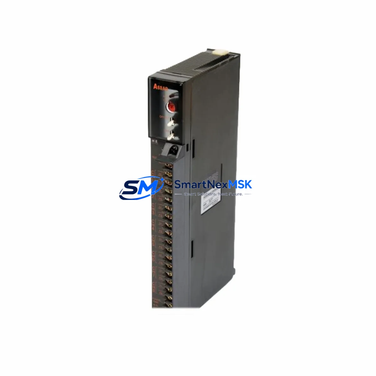
The MITSUBISHI QX524 (part number BN634A636G51) is a 32-point DC input module designed for the Melsec-Q series programmable logic controller platform. As a maintenance-critical spare, this module supports rapid fault isolation and system restoration in industrial environments where unplanned downtime carries significant operational and financial risk. Whether you are managing a scheduled overhaul, responding to an emergency fault, or building a strategic spare parts inventory, the QX524 BN634A636G51 provides a verified, original replacement that maintains full compatibility with the Q-series backplane and CPU architecture.
Maintenance engineers working on Melsec-Q systems recognize the QX524 as a high-reliability digital input module used across a wide range of discrete signal acquisition tasks — from field sensor inputs and limit switch feedback to pushbutton interlocks and proximity detector signals. Its 32-channel capacity makes it a common fixture in mid-to-large control cabinets, and its failure can affect entire process segments. Stocking this module as a ready spare is a standard practice in facilities operating Q02, Q06, Q12, or Q25 series CPU configurations.
From a procurement engineering perspective, sourcing the QX524 BN634A636G51 through a verified industrial supplier with pre-shipment testing and documented warranty coverage eliminates the risk of receiving counterfeit or refurbished units that may pass initial inspection but fail under load. Every unit we supply is inspected, function-tested, and shipped with a 12-month warranty against manufacturing defects.
Spare Maintenance Table
| Parameter | Specification |
|---|---|
| Model | QX524 |
| Part Number | BN634A636G51 |
| Brand | MITSUBISHI Electric |
| Series | Melsec-Q (Q-Series) |
| Module Type | Digital Input Module (DC Input) |
| Input Points | 32 Points |
| Input Voltage | 24 VDC |
| Isolation Method | Photocoupler isolation |
| Compatible CPUs | Q02, Q06H, Q12H, Q25H, Q02U, Q06UDH and compatible Q-series CPUs |
| Backplane Compatibility | Q-series main base unit / extension base unit |
| Installation | DIN rail / base unit slot mount |
| Operating Temperature | 0°C to 55°C |
| Storage Temperature | -25°C to 75°C |
| Origin | Japan |
| Condition | Original, New |
| Pre-Shipment Testing | Yes — function verified before dispatch |
| Warranty | 12 Months |
Maintenance Planning for Continuous Operation
When replacing the QX524 BN634A636G51 in a Melsec-Q control cabinet, a thorough maintenance inspection should extend beyond the module itself. Experienced maintenance engineers treat a digital input module failure as a trigger for a broader cabinet health check to prevent cascading faults and reduce the likelihood of repeat downtime.
Begin by inspecting the Q-series power supply module (such as the Q61P or Q62P) that feeds the base unit. A degraded power supply can cause intermittent input faults that mimic module failure. Check output voltage stability under load before reinstalling the replacement QX524. Next, verify the Q-series main base unit (e.g., Q33B or Q65B) for slot connector wear or contamination, as poor backplane contact is a common root cause of I/O module errors in aging systems.
Inspect all terminal block wiring connected to the QX524’s 40-pin connector. Loose or corroded field wiring is a frequent source of false input signals. If the system uses signal isolators between field devices and the PLC input, verify isolator output levels are within the QX524’s rated input threshold. For systems with relay output modules (such as the QY10 or QY18A) in the same cabinet, check relay contact condition and coil voltage, as relay chatter can introduce noise on shared DC commons.
If the Melsec-Q system includes a QJ71C24N serial communication module or a QJ71E71-100 Ethernet module, confirm that communication parameters and network addresses remain intact after the module swap — some CPU configurations require re-initialization of the I/O map following a slot change. For systems using QD75 positioning modules or QA1S6ADP extension adapters, verify that the I/O assignment table in GX Works2 or GX Developer reflects the correct slot configuration after replacement.
Finally, review the fuse and circuit protection on the 24 VDC field supply feeding the QX524 input commons. A blown fuse or tripped breaker on the field supply is often the actual fault, with the module itself undamaged. Confirming field supply integrity before condemning the module can save significant time and cost.
Site Replacement Workflow
Replacing the QX524 BN634A636G51 on-site is a straightforward procedure when the correct spare is available and the replacement workflow is followed systematically. Begin by placing the affected CPU in STOP mode via the RUN/STOP switch or through GX Works2 remote operation. Record the current I/O diagnostic status and any active error codes from the CPU’s LED indicators or the engineering software before powering down the base unit.
Power down the base unit and disconnect the 40-pin field wiring connector from the QX524. Label all wiring if not already documented. Remove the module from its slot by releasing the module locking lever and sliding it out. Insert the replacement QX524 BN634A636G51 into the same slot, ensuring the module locks securely into the backplane connector. Reconnect the field wiring connector and restore power to the base unit.
After power-up, confirm that the QX524’s RUN LED illuminates and that no ERR LED is active. Use GX Works2 or GX Developer to perform an I/O refresh check and verify that all 32 input channels respond correctly to field signals. If the system previously used a different firmware revision or if the CPU detects a module type mismatch, re-download the system parameters to clear the error. Document the replacement in the maintenance log, including the date, replaced part number, and post-replacement test results.
For facilities managing legacy Q-series systems approaching end-of-life, maintaining a minimum stock of one to two QX524 units per production line is a widely adopted strategy to ensure rapid recovery from unplanned failures without waiting on lead times from standard distribution channels.
Spare Parts Support FAQ
Q: Is the QX524 BN634A636G51 compatible with both Q-series main base units and extension base units?
A: Yes. The QX524 is designed for use in any Q-series base unit slot, including main base units (Q33B, Q52B, Q55B, Q65B, Q68B, Q612B) and extension base units. Confirm slot availability and I/O assignment in your system parameter settings before installation.
Q: What is the warranty coverage and what does it include?
A: Every QX524 BN634A636G51 supplied by SMARTNEXMSK carries a 12-month warranty covering manufacturing defects and functional failure under normal operating conditions. Units are function-tested before shipment. Warranty does not cover damage resulting from incorrect installation, overvoltage, or physical mishandling.
Q: How do I verify the module is genuine before installation?
A: Genuine MITSUBISHI QX524 modules carry the MITSUBISHI Electric logo, model label, and part number on the module housing. The BN634A636G51 part number should be clearly printed on the label. We recommend verifying the module’s response in GX Works2 I/O diagnostics immediately after installation as a functional acceptance test.
Q: What is the recommended spare parts stocking strategy for Melsec-Q digital input modules?
A: For production-critical systems, maintain at least one QX524 per control cabinet as a hot spare. For facilities with multiple Q-series lines, a centralized spare parts store with two to three units provides adequate coverage for most failure scenarios. Pair the QX524 with a spare Q-series power supply module and a set of terminal block connectors to ensure a complete recovery kit is available at all times.
© 2026 SMARTNEXMSK. All rights reserved.
Original Source: https://smartnexmsk.com
Contact: sales@smartnexmsk.com | +86 18259474341