Mitsubishi BC186A032G54 A24PW7.5D Retrofit-Ready Power Supply for MELSEC-A Control Systems
The Mitsubishi Electric BC186A032G54 A24PW7.5D is a proven retrofit-ready power supply module engineered for MELSEC-A series programmable logic controller systems. As Mitsubishi Electric progressively phases out the MELSEC-A platform in favour of the MELSEC-Q and MELSEC-iQ-R series, the demand for reliable, verified replacement units for the A24PW7.5D has grown significantly across manufacturing, utilities, and process automation sectors. This unit provides a direct, drop-in power supply solution for existing A-series base units and racks, enabling plant engineers to extend operational life, reduce unplanned downtime, and defer full system migration until a planned maintenance window.
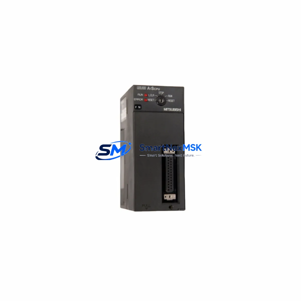
The BC186A032G54 A24PW7.5D delivers 24 VDC output at 7.5 A continuous rated current, designed to power A-series CPU modules such as the A2UCPU, A3UCPU, and A1SCPU, as well as associated I/O modules mounted on A1S-series and A3-series base units. When replacing a failed or degraded power supply in an existing control cabinet, engineers must verify the input voltage range (100–240 VAC, 50/60 Hz), confirm the output current capacity against the total module load on the backplane, and inspect the terminal block wiring layout before installation. The terminal arrangement on the A24PW7.5D is compatible with standard MELSEC-A rack mounting slots, and no backplane modification is required for a like-for-like swap.
Upgrade Compatibility Table
| Parameter | BC186A032G54 A24PW7.5D | Notes / Retrofit Guidance |
|---|---|---|
| Output Voltage | 24 VDC | Verify all downstream modules accept 24 VDC supply |
| Rated Output Current | 7.5 A | Calculate total I/O module current draw before replacement |
| Input Voltage Range | 100–240 VAC, 50/60 Hz | Compatible with global plant supply voltages |
| Mounting Interface | MELSEC-A series base unit slot | Direct fit; no backplane modification required |
| Compatible CPU Modules | A2UCPU, A3UCPU, A1SCPU, A2ACPU | Confirm CPU model before ordering |
| Compatible Base Units | A1S38B, A1S55B, A1S65B, A38B | Check rack slot count and power budget |
| Communication Compatibility | MELSEC-A bus protocol | No protocol migration required for like-for-like swap |
| Replacement Recommendation | Direct drop-in for A24PW7.5D | Retain original terminal wiring diagram |
| Commissioning Focus | Output voltage check, load test | Measure 24 VDC at terminal block post-installation |
| Warranty | 12 Months | Covers manufacturing defects; includes pre-shipment functional test |
Retrofit Planning for Existing Automation Systems
Successful retrofit of the A24PW7.5D begins with a thorough audit of the existing control cabinet. Engineers should document the current wiring at the power supply terminal block, noting the AC input connections, the 24 VDC output distribution to the A-series base unit, and any auxiliary 24 VDC feeds to field devices or HMI panels. The A1S38B or A38B base unit backplane must be inspected for physical damage or oxidation at the power supply connector before the replacement unit is seated.
In systems where the MELSEC-A CPU module — such as the A2UCPU or A3UCPU — is still operational, the replacement power supply can be installed without disturbing the CPU program memory, provided the CPU is powered down cleanly and the battery-backed RAM retains the ladder logic. Engineers should confirm the A6BAT or A7BAT battery condition before commencing work, as a depleted battery during a power interruption will result in program loss and require re-download from the programming tool via an SC-09 or USB-SC09-FX programming cable.
Where the retrofit scope extends beyond the power supply, it is common to simultaneously replace aging A1SX40 or A1SY40 I/O modules, inspect the A1SJ71UC24-R2 or A1SJ71E71-B5 communication modules for firmware currency, and verify that the GOT1000 or GOT2000 series HMI screens remain correctly mapped to the existing device addresses. If the site operates MELSEC-A modules alongside a newer Q-series rack via an inter-bus link, the A1SJ61BT11 CC-Link master module wiring and station address settings must be re-confirmed after power restoration.
For sites planning a phased migration from MELSEC-A to MELSEC-Q, the A24PW7.5D replacement extends the operational window of the A-series rack while Q-series hardware — including the Q62P or Q63P power supply modules, QX40 or QY40P I/O modules, and QJ71C24N serial communication modules — is procured and staged. This approach minimises capital expenditure in any single budget period and allows engineering teams to validate the new Q-series program offline before cutover.
Downtime Control During System Migration
Minimising production downtime during a power supply replacement on a live MELSEC-A system requires careful pre-planning. The recommended approach is to schedule the replacement during a planned maintenance window, prepare the replacement A24PW7.5D unit on the bench with a pre-shipment functional test completed, and have the original wiring diagram and PLC program backup available before the panel is de-energised.
Prior to shutdown, the engineer should use GX Developer or GX Works2 to perform a full program upload from the A2UCPU or A3UCPU to a laptop, verifying the checksum against the last known-good backup. The CPU module should be placed in STOP mode before the main breaker is opened. After the replacement power supply is installed and the terminal block connections are torqued to specification, the system should be energised with a clamp meter on the 24 VDC output to confirm rated voltage before the CPU is switched to RUN mode.
Field I/O should be verified in sequence — digital inputs first, then digital outputs under manual forcing — before releasing the system to automatic control. HMI communication links to the GOT series panel should be confirmed active, and any CC-Link or MELSEC-NET/H network segments should be checked for normal data link status before handover. A well-prepared replacement of the BC186A032G54 A24PW7.5D can typically be completed within a two-to-four hour maintenance window, preserving production continuity and avoiding unplanned line stoppages.
Retrofit Support FAQ
Q1: Is the BC186A032G54 A24PW7.5D a direct replacement for the original A24PW7.5D power supply?
Yes. The BC186A032G54 is the Mitsubishi Electric board-level part number for the A24PW7.5D power supply module. It is a direct, like-for-like replacement compatible with all MELSEC-A series base units that accept the A24PW7.5D, including the A1S38B, A1S55B, A1S65B, and A38B racks. No hardware modification or parameter change is required.
Q2: What pre-installation checks are required before fitting the replacement unit?
Before installation, verify the total current draw of all modules mounted on the base unit does not exceed 7.5 A. Inspect the backplane connector for damage, confirm the AC input wiring is correctly rated, and ensure the CPU battery is serviceable. A program backup via GX Developer or GX Works2 is strongly recommended before de-energising the panel.
Q3: How is the replacement unit tested before shipment?
Each BC186A032G54 A24PW7.5D unit undergoes a pre-shipment functional test covering output voltage accuracy, load regulation, and insulation resistance. Units are supplied with a 12-month warranty covering manufacturing defects. Test records are available on request for quality-critical applications.
Q4: Can this power supply support a mixed MELSEC-A and MELSEC-Q migration rack configuration?
The A24PW7.5D is specific to the MELSEC-A series rack and cannot be used in a MELSEC-Q or MELSEC-iQ-R base unit. For mixed-platform migration projects, the A-series rack retains the A24PW7.5D while the Q-series rack uses a dedicated Q62P or Q63P power supply. Inter-rack communication is maintained via the A1SJ61BT11 CC-Link module or MELSEC-NET/H link module during the transition period.
© 2026 SMARTNEXMSK. All rights reserved.
Original Source: https://smartnexmsk.com
Contact: sales@smartnexmsk.com | +86 18259474341