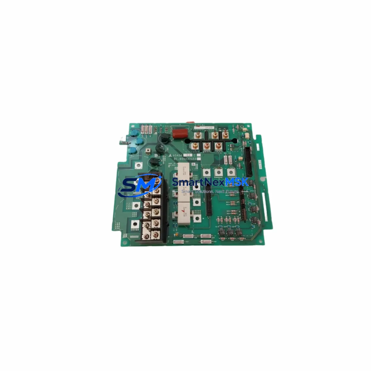
Mitsubishi BC186A166H03 Retrofit-Ready Servo Drive PCB for MELSERVO Control Systems
The Mitsubishi Electric BC186A166H03 is a servo drive printed circuit board (PCB) engineered for use within the MELSERVO series of AC servo amplifiers. As legacy servo systems age and OEM support windows close, the BC186A166H03 has become a critical retrofit component for engineers tasked with modernizing or restoring servo-driven axes on production lines, CNC machining centers, injection molding machines, and automated assembly equipment. Whether you are replacing a failed board in an MR-J2S, MR-J3, or transitioning a multi-axis system toward a more maintainable architecture, this PCB provides a verified, stock-available path to restoring full servo performance without a complete drive replacement.
Our inventory of BC186A166H03 units is sourced from authorized distribution channels and subjected to outgoing functional testing prior to shipment. Each unit is covered by a 12-month warranty against manufacturing defects and operational failure under normal service conditions. Fast dispatch from bonded warehouse stock ensures minimal disruption to your production schedule.
Upgrade Compatibility Table
| Parameter | Details |
|---|---|
| Part Number | BC186A166H03 |
| Manufacturer | Mitsubishi Electric |
| Compatible Series | MELSERVO MR-J2S, MR-J3, MR-J2M (verify amplifier model before ordering) |
| Component Type | Servo Drive Control / Power PCB |
| Mounting Interface | Internal backplane connector; matches OEM slot specification |
| Communication Compatibility | SSCNET / SSCNET III (subject to host amplifier model) |
| Replacement Scope | Direct board-level replacement; no firmware re-flash required in most configurations |
| Installation Requirement | ESD precautions; power-off and capacitor discharge before handling |
| Commissioning Note | Verify servo parameter backup (MR Configurator2) before swap; restore after installation |
| Warranty | 12 months from date of shipment |
| Origin | Japan |
| Outgoing Test | Functional test performed prior to dispatch |
Retrofit Planning for Existing Automation Systems
A successful BC186A166H03 retrofit begins well before the board is physically swapped. Engineers working on MELSERVO-based systems should start by auditing the full servo cabinet: confirm the host servo amplifier model (e.g., MR-J2S-100A or MR-J3-200A), document the existing wiring harness pinout at the CN1 and CN2 connectors, and verify that the MR-J2S power supply module or dedicated 24 VDC control power rail is within specification. Voltage sag on the control power bus is a common root cause of PCB failure and must be corrected before installing a replacement board.
For multi-axis systems running on an SSCNET fiber-optic ring, inspect the SSCNET III optical cable routing between the motion controller (typically an MELSEC Q172DCPU or Q173DCPU motion CPU) and each amplifier node. A degraded fiber link can cause axis communication errors that mimic PCB failure; always perform a loopback test before condemning the board. If the system uses a MELSEC Q-series CPU with a QD75MH positioning module, confirm that the axis parameter table and home position data are backed up to the CPU memory card or engineering workstation running GX Works2 or MT Works2.
Terminal block wiring at the servo amplifier’s TB1 (main circuit) and TB2 (control circuit) should be photographed and labeled before disassembly. Pay particular attention to the regenerative resistor connection and the dynamic brake resistor circuit if an external MR-RB resistor unit is installed. Incorrect reconnection of the regenerative circuit after a board swap can result in overvoltage faults or thermal damage on first power-up.
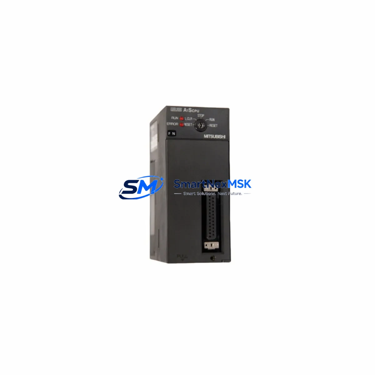
If the retrofit is part of a broader control cabinet upgrade that includes replacing an aging MELSEC A-series PLC (e.g., A2USCPU or A3UCPU) with a modern MELSEC iQ-R series RCPU, plan the servo communication migration carefully. The A-series motion network uses a different protocol stack than SSCNET III/H, and intermediate gateway modules or a full amplifier upgrade to the MR-J4 series may be required. In such cases, the BC186A166H03 serves as a cost-effective bridge solution: restore the existing MELSERVO axis to full operation first, stabilize production, then execute the broader platform migration in a planned maintenance window.
For I/O-intensive applications, verify that the MR-J3-D05 safety logic unit or any external MELSEC QX40 input module connected to the servo enable and alarm reset circuits is functioning correctly. A faulty I/O module that holds the servo-ready signal low will prevent the replacement PCB from enabling the axis, leading to unnecessary diagnostic time on the new board.
Downtime Control During System Migration
Minimizing unplanned downtime during a servo PCB replacement requires a structured approach. Before powering down the affected axis, use MR Configurator2 to export the full parameter set (PA, PB, PC, PD, PE groups) and save the servo tuning data to a local file. If the amplifier is part of a multi-axis SSCNET ring, note the axis number assignment in the motion controller project — axis numbering must be preserved after the board swap to avoid a mismatch between the motion program and the physical drive.
Isolate the affected drive from the main circuit by opening the MCCB or contactor upstream of the amplifier’s L1/L2/L3 terminals. Allow a minimum of 15 minutes for the DC bus capacitors to discharge before opening the amplifier enclosure. Use a calibrated voltmeter to confirm bus voltage is below 30 VDC before touching internal components. Ground yourself with an ESD wrist strap and work on an anti-static mat.
After installing the BC186A166H03, restore the parameter file via MR Configurator2 before enabling the axis. Perform a JOG operation at low speed to confirm encoder feedback, direction of rotation, and brake release timing before returning the axis to automatic mode. If the system uses an HMI panel (e.g., Mitsubishi GOT2000 series GT2710-VTBA) with servo status screens, verify that all axis status tags update correctly after the swap. Document the replacement in the machine maintenance log, including the new board serial number and the date of installation, to support future warranty claims and traceability.
For facilities with strict OEE targets, consider pre-staging a tested spare BC186A166H03 in the local spare parts cabinet. Paired with a pre-configured parameter backup file stored on a GOT CF card or engineering laptop, a trained technician can complete the board swap and axis recommission in under two hours, keeping unplanned downtime within acceptable limits.
Retrofit Support FAQ
Q1: Is the BC186A166H03 a direct drop-in replacement for my existing MELSERVO servo drive PCB?
In most MR-J2S and MR-J3 series amplifiers, the BC186A166H03 is a board-level replacement that fits the OEM slot without mechanical modification. However, servo amplifier PCB configurations can vary by production revision. We recommend confirming your amplifier’s model number and production date code with our technical team before ordering to ensure full compatibility.
Q2: What commissioning steps are required after installing the BC186A166H03?
Restore your servo parameter backup using MR Configurator2 before enabling the axis. Perform a low-speed JOG test to verify encoder feedback and rotation direction. Check alarm history for any residual fault codes. If the amplifier is on an SSCNET ring, confirm axis communication status in the motion controller before returning to automatic operation. No firmware re-flash is required in standard replacement scenarios.
Q3: How do I verify wiring compatibility before powering up after the board swap?
Compare your pre-disassembly wiring photographs against the amplifier’s terminal diagram in the MR-J2S or MR-J3 hardware manual. Confirm CN1 (I/O connector), CN2 (encoder connector), TB1 (main circuit), and TB2 (control circuit) connections. Pay special attention to the regenerative resistor terminals and the 24 VDC control power polarity. Use a continuity tester to verify no cross-wiring before applying power.
Q4: What does the 12-month warranty cover, and what is the claims process?
The 12-month warranty covers manufacturing defects and operational failure under normal service conditions from the date of shipment. It does not cover damage caused by incorrect installation, overvoltage, ESD mishandling, or unauthorized modification. To initiate a warranty claim, contact our sales team with your order number, the unit serial number, and a description of the fault. We will arrange return shipping and provide a replacement or repair within the agreed service lead time.
© 2026 SMARTNEXMSK. All rights reserved.
Original Source: https://smartnexmsk.com
Contact: sales@smartnexmsk.com | +86 18259474341