Mitsubishi BC386A504G51A Maintenance-Ready Spare MELSEC-A: Spare Replacement & Industrial Downtime Risk Control
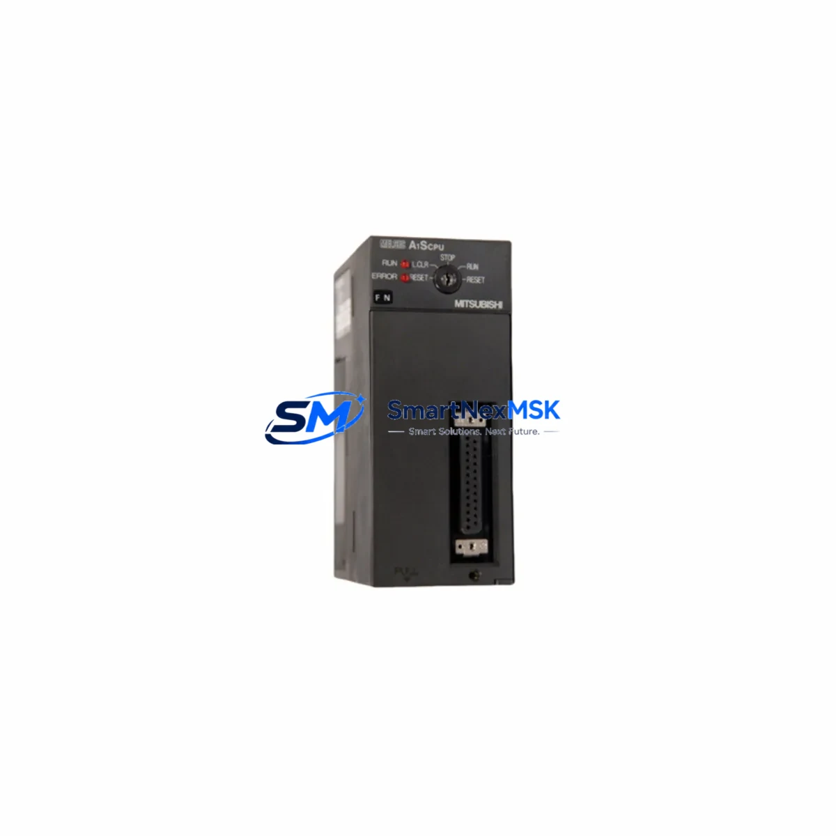
The Mitsubishi Electric BC386A504G51A is a CPU base unit designed for the MELSEC-A Series programmable logic controller platform — one of the most widely deployed legacy PLC architectures in discrete manufacturing, process control, and material handling automation. As original production of MELSEC-A hardware approaches end-of-life, maintaining a verified spare of the BC386A504G51A has become a critical element of any plant maintenance strategy. Unplanned downtime caused by a failed base unit can halt an entire production line; having a tested, warranty-backed replacement on the shelf is the most direct way to compress mean time to repair (MTTR) and protect operational continuity.
This unit is supplied as an original Mitsubishi Electric component — not a counterfeit, not a refurbished pull, and not a third-party clone. Each unit undergoes pre-shipment functional verification and ships with a 12-month warranty covering manufacturing defects and operational failure under normal service conditions. For maintenance engineers managing aging MELSEC-A installations, this represents a low-risk, high-confidence procurement path.
Spare Maintenance Table
| Parameter | Specification / Detail |
|---|---|
| Part Number / SKU | BC386A504G51A |
| Brand | Mitsubishi Electric |
| Series | MELSEC-A (A Series PLC) |
| Product Type | CPU Base Unit |
| Compatible CPU Modules | A2USCPU, A2USHCPU, A3UCPU, A4UCPU and compatible MELSEC-A CPU variants |
| Slot Configuration | Multi-slot base for I/O and special function module expansion |
| Power Supply Compatibility | Designed for use with MELSEC-A series power supply modules (e.g. A1S61PN, A1S62PN) |
| Backplane Bus | MELSEC-A parallel bus architecture |
| Installation Environment | Industrial control cabinet; operating temperature 0–55 °C, humidity 10–90% RH non-condensing |
| Origin | Japan |
| Condition | Original, new or surplus stock — pre-shipment tested |
| Warranty | 12 months from date of shipment |
| Lead Time | In-stock; ships within 1–3 business days |
| Maintenance Recommendation | Inspect backplane connectors and bus contacts during scheduled PM; replace if corrosion or mechanical wear is detected |
Maintenance Planning for Continuous Operation
When a MELSEC-A base unit such as the BC386A504G51A is flagged for replacement during a planned shutdown or emergency callout, experienced maintenance engineers treat the event as a trigger for a broader cabinet inspection. The base unit is the physical and electrical backbone of the entire rack — every module seated in it depends on the integrity of its bus connectors, power distribution traces, and slot keying. A failure here often indicates that adjacent components have been operating under stress.
Start with the power supply module. MELSEC-A racks typically run on dedicated power supply units such as the A1S61PN or A1S62PN; measure output voltage under load before reinstalling the CPU. Next, inspect the CPU module itself — the A2USCPU or A3UCPU seated in the base should be checked for battery backup status and program retention. If the base unit failure was caused by a surge or transient, the CPU’s internal memory and clock battery may also need attention.
I/O modules installed in the rack — including digital input modules like the AX40S and digital output modules such as the AY40 — should be reseated and their terminal blocks inspected for loose wiring or oxidized contacts. Analog I/O modules, if present, may require re-calibration after a power interruption. Communication modules such as the A1SJ71UC24-R4 (RS-232C/RS-422 interface) or Ethernet interface cards should be verified for correct parameter settings after the base swap.
For systems using MELSEC-A remote I/O, check the A1SJ61BT11 CC-Link master module and confirm that the network topology and station addresses are intact. Signal isolators and surge protectors installed on analog input channels are often overlooked during base unit replacements — verify that these passive components have not been damaged by the same fault event that caused the base failure.
Finally, review the terminal blocks and wiring harnesses connected to the I/O modules. Loose field wiring is a common secondary cause of recurring base unit stress. A thorough torque check of all terminal screws and a visual inspection of cable routing inside the control cabinet will reduce the likelihood of repeat failures after the BC386A504G51A is installed.
Site Replacement Workflow
Step 1 — Isolation & Documentation: De-energize the control cabinet following your site LOTO procedure. Photograph the existing rack layout, module positions, and wiring before removal. Note the slot assignments of all installed modules.
Step 2 — Module Extraction: Remove all I/O, communication, and special function modules from the existing base unit in sequence. Label each module with its slot number. Carefully disconnect the power supply wiring from the base.
Step 3 — Base Unit Removal: Unscrew the BC386A504G51A (or its predecessor) from the DIN rail or panel mount. Inspect the mounting surface and DIN rail clip for deformation.
Step 4 — New Base Installation: Mount the replacement BC386A504G51A. Verify that the DIN rail clip is fully engaged and the unit is mechanically secure. Reconnect power supply wiring to the correct terminals, observing polarity and torque specifications.
Step 5 — Module Reinsertion: Reinstall all modules in their original slot positions. Ensure each module is fully seated and the locking lever is engaged. Reconnect field wiring terminal blocks.
Step 6 — Power-Up & Verification: Energize the cabinet and observe the CPU status LEDs. Confirm that the CPU module enters RUN mode and that all I/O modules report normal status. Verify communication links to remote I/O and HMI panels (e.g., GOT1000 or GOT2000 series HMI) are re-established.
Step 7 — Functional Test: Execute a controlled functional test of the process or machine before returning to production. Document the replacement in the site maintenance log, including the new unit’s serial number and warranty start date.
This workflow is designed to minimize downtime and ensure that the replacement base unit is installed in a system that has been verified to be free of secondary faults — protecting both the new spare and the broader control system investment.
Spare Parts Support FAQ
Q1: Is the BC386A504G51A still available as a new original part?
A: Yes. We maintain stock of original Mitsubishi Electric BC386A504G51A units sourced through authorized industrial distribution channels. Each unit is inspected and tested prior to shipment. Given the MELSEC-A platform’s legacy status, we recommend procuring at least one additional spare to protect against future supply constraints.
Q2: How do I verify compatibility with my existing MELSEC-A rack configuration?
A: The BC386A504G51A is compatible with the standard MELSEC-A CPU and module lineup. Confirm your CPU model (e.g., A2USCPU, A3UCPU), the number of slots required, and your power supply module type before ordering. If you share your existing rack configuration or system drawing, our technical team can confirm compatibility before shipment.
Q3: What does the 12-month warranty cover, and what is the claims process?
A: The 12-month warranty covers manufacturing defects and operational failure under normal industrial service conditions. It does not cover damage caused by incorrect installation, overvoltage events, or physical mishandling. To initiate a warranty claim, contact us with the order reference, unit serial number, and a description of the fault. We will arrange return, inspection, and replacement or repair within the warranty period.
Q4: Can you supply other MELSEC-A components to complete my spare parts kit?
A: Yes. We stock a broad range of MELSEC-A series components including CPU modules, power supply units, digital and analog I/O modules, communication modules, and base units of various slot configurations. Contact us with your BOM or spare parts list and we will provide availability and pricing for the complete kit.
© 2026 SMARTNEXMSK. All rights reserved.
Original Source: https://smartnexmsk.com
Contact: sales@smartnexmsk.com | +86 18259474341