Mitsubishi CM150DY-24A Retrofit-Ready IGBT Module for NF Series Control Systems
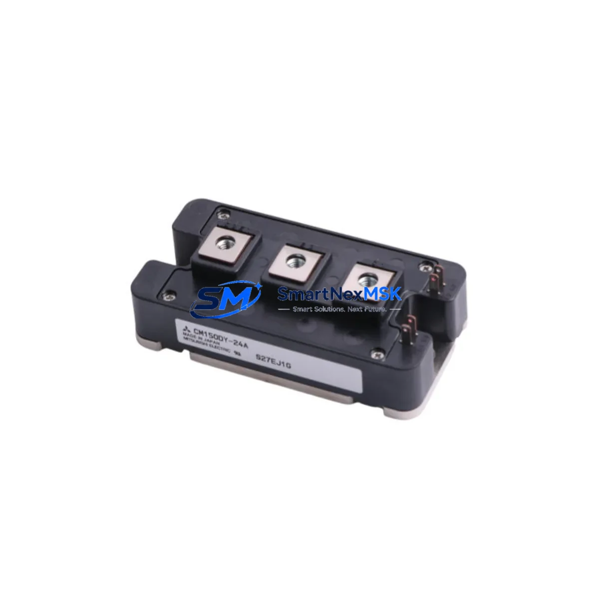
The Mitsubishi CM150DY-24A is a 150A / 1200V dual IGBT power module engineered for seamless compatibility with Mitsubishi NF Series variable frequency drives and legacy industrial control systems. As original NF Series drive platforms approach end-of-life and spare parts become increasingly scarce, the CM150DY-24A remains one of the most sought-after retrofit components for engineers tasked with extending the operational life of existing automation infrastructure without full system replacement.
Whether you are managing a planned upgrade cycle or responding to an unplanned drive failure on the production floor, the CM150DY-24A provides a verified drop-in solution that preserves your existing control architecture, minimizes rewiring, and eliminates the need to retrain operators on new HMI interfaces. SMARTNEXMSK maintains ready stock of this module, fully tested and backed by a 12-month warranty.
Upgrade Compatibility Table
| Parameter | CM150DY-24A Specification | Retrofit Notes |
|---|---|---|
| Collector Current (Ic) | 150A | Verify drive gate driver board current rating matches |
| Collector-Emitter Voltage (Vces) | 1200V | Suitable for 690V AC input drive platforms |
| Module Configuration | Dual (2-in-1) IGBT | Direct replacement for same-footprint dual modules |
| Package / Mounting | Standard flat-base with M6 screw terminals | Confirm heatsink flatness and thermal compound application |
| Gate Drive Voltage | +15V / -8V recommended | Verify existing gate driver board output levels |
| Communication Compatibility | N/A (power stage component) | Upper-level PLC and SCADA links unaffected |
| Replacement Scope | Drop-in for NF Series drive power stage | No firmware changes required in most applications |
| Warranty | 12 Months | Covers manufacturing defects; includes pre-shipment functional test |
Retrofit Planning for Existing Automation Systems
A successful CM150DY-24A retrofit begins well before the module arrives on site. Engineers should start by pulling the existing drive’s wiring diagram and confirming the DC bus voltage, gate driver supply rails, and thermistor circuit connections. In many NF Series installations, the gate driver board — often a dedicated PCB mounted directly above the power module — interfaces with the CM150DY-24A via a low-profile connector. Inspect this connector for carbon tracking or heat damage before reinstalling.
On the control side, the host PLC — frequently a Mitsubishi MELSEC Q Series or FX5U CPU module — communicates with the drive via CC-Link or MODBUS RTU. Confirm that the communication parameters stored in the PLC program (station address, baud rate, parity) are documented before powering down, as some older drives reset communication settings on a cold restart. If the drive is connected to a Mitsubishi GOT2000 HMI, verify that the HMI screen tags referencing drive status words remain valid after the module swap — the CM150DY-24A replacement does not alter the drive’s register map, so HMI screens should remain fully functional.
For systems using a Mitsubishi FR-A800 Series or FR-F800 Series drive as the host inverter, the CM150DY-24A is a recognized power stage component. When replacing the module in these platforms, also inspect the QX40 or QX80 digital input modules connected to the control cabinet for any fault interlock signals that may have been triggered by the original module failure. Reset these interlocks in the PLC program before attempting a test run.
I/O expansion cards such as the Mitsubishi QD75MH positioning module or analog output modules like the Q68DAV should be checked for any parameter loss if the control cabinet experienced a power surge coinciding with the IGBT failure. Back up all module parameters using GX Works3 or GX Works2 before the retrofit begins. If the system uses a Mitsubishi MR-J4 servo amplifier in the same cabinet, verify that the servo’s regenerative resistor and braking circuit were not affected by the fault event.
Finally, for cabinets using a Mitsubishi NZ2GF2B1-16D remote I/O module on CC-Link IE Field, confirm network topology continuity after the drive is returned to service. A module swap that involves even brief bus interruption can cause CC-Link IE Field stations to drop offline and require a manual network reset from the engineering workstation.
Downtime Control During System Migration
Minimizing production downtime during a CM150DY-24A replacement requires a structured approach. Begin by scheduling the swap during a planned maintenance window and preparing a pre-tested spare module in advance — SMARTNEXMSK ships modules with a pre-shipment functional test report, allowing your team to confirm the unit is operational before the maintenance window opens.
Before de-energizing the drive, use the PLC’s online monitoring function in GX Works3 to capture a snapshot of all current parameter values, including acceleration/deceleration ramps, torque limits, and carrier frequency settings. Store this snapshot to a CF card or USB memory connected to the CPU module. This ensures that if the drive’s internal EEPROM was corrupted by the fault, parameters can be restored in minutes rather than hours.
During the physical swap, discharge the DC bus capacitors fully — typically a minimum of 10 minutes after power-off — and verify with a calibrated DC voltmeter before touching any bus bar connections. Apply fresh thermal compound to the heatsink interface, torque the module mounting screws to the manufacturer’s specification (typically 3–4 N·m for M6 fasteners), and reconnect gate driver and thermistor leads in the correct sequence.
After reinstallation, perform a no-load test run at low speed before restoring the full production load. Monitor the module’s case temperature via the drive’s built-in thermal monitoring or an external thermocouple for the first 30 minutes of operation. This staged commissioning approach protects both the new module and the connected mechanical load, and keeps the overall outage window to under four hours in most retrofit scenarios.
Retrofit Support FAQ
Q1: Is the CM150DY-24A a direct replacement for the original module in my NF Series drive, or are there wiring modifications required?
The CM150DY-24A is designed as a direct drop-in replacement for the same-rated module in Mitsubishi NF Series drive platforms. Terminal layout, mounting footprint, and gate driver interface are identical to the original. No wiring modifications are required in standard applications, though we recommend verifying gate driver supply voltage levels before powering up.
Q2: What pre-shipment testing does SMARTNEXMSK perform on the CM150DY-24A?
Each unit undergoes a functional test covering gate threshold voltage, collector-emitter leakage current, and on-state voltage drop before shipment. A test report is included with every order. The module is covered by a 12-month warranty against manufacturing defects from the date of shipment.
Q3: My drive tripped on an overcurrent fault before the module failed. Do I need to check anything else in the cabinet before replacing the IGBT?
Yes. An overcurrent trip can stress the gate driver board, DC bus capacitors, and current sensors simultaneously. Before installing the new CM150DY-24A, inspect the gate driver PCB for burnt resistors or damaged optocouplers, check DC bus capacitor ESR if possible, and verify that the current sensor output signals are within the drive’s specified range. Replacing only the IGBT module without addressing upstream fault causes is the most common reason for repeat failures.
Q4: Can SMARTNEXMSK supply other components needed for a complete NF Series drive retrofit?
Yes. In addition to the CM150DY-24A, we maintain stock of related components commonly required in NF Series retrofit projects, including gate driver boards, DC bus capacitor banks, control power supply boards, and fan assemblies. Contact our technical team with your drive model number for a complete bill of materials assessment.
© 2026 SMARTNEXMSK. All rights reserved.
Original Source: https://smartnexmsk.com
Contact: sales@smartnexmsk.com | +86 18259474341