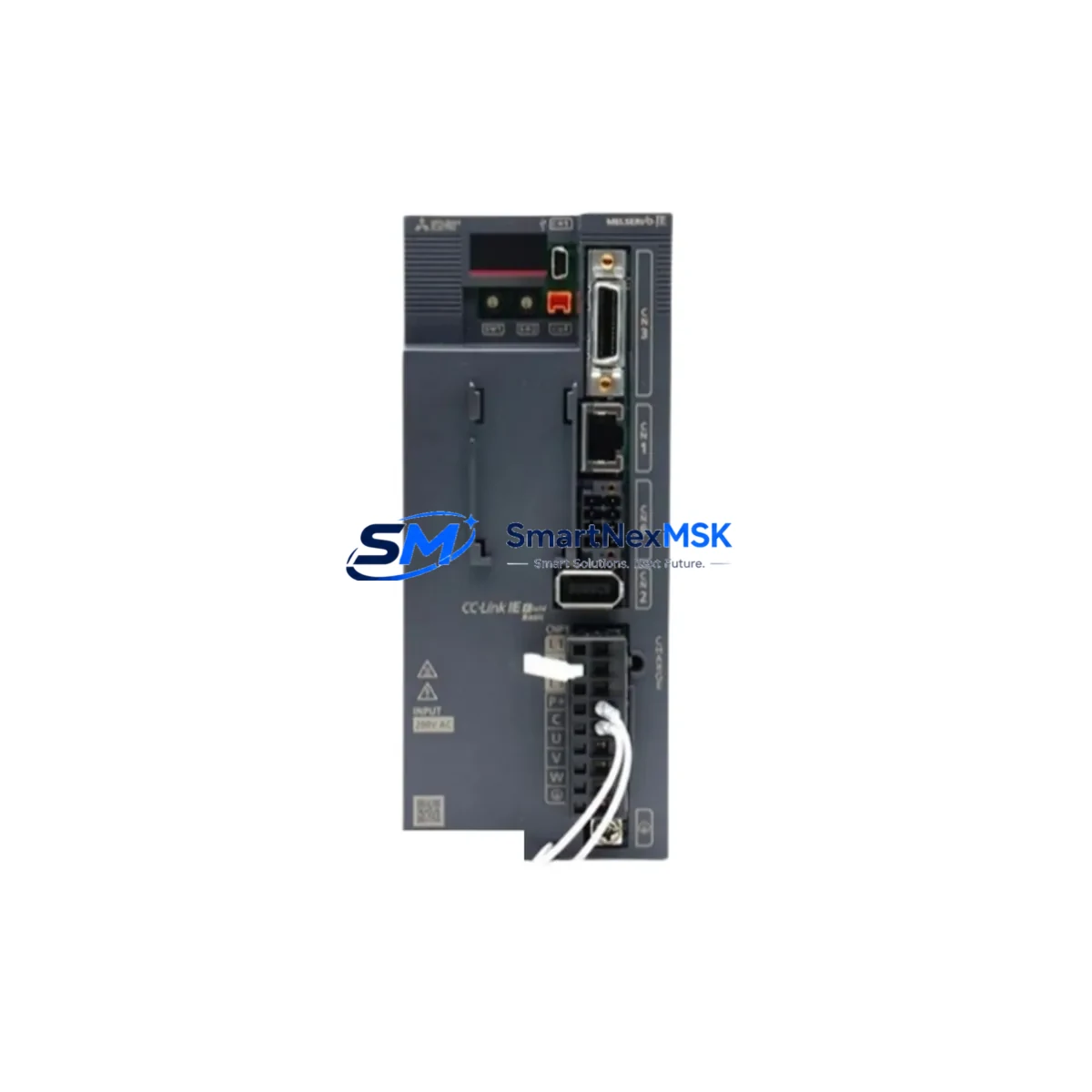
Mitsubishi MR-JE-70C Retrofit-Ready AC Servo Amplifier for MELSERVO-JE Control Systems
The Mitsubishi MR-JE-70C is a 750W AC servo amplifier from the MELSERVO-JE series, engineered for seamless integration into existing Mitsubishi servo control architectures. Whether you are replacing an end-of-life MR-E-70A, retiring a legacy MR-J2S-70CP, or upgrading a multi-axis panel from an older MR-J3 platform, the MR-JE-70C delivers a cost-effective, drop-in-compatible modernization path with minimal disruption to your production line.
Designed for industrial environments where uptime is non-negotiable, the MR-JE-70C supports CC-Link IE Field Network communication, enabling direct integration with Mitsubishi MELSEC iQ-R and MELSEC iQ-F series PLCs without gateway hardware. Its USB-based MR Configurator2 interface simplifies parameter migration from older amplifier generations, allowing engineers to import legacy gain settings, electronic gear ratios, and homing sequences directly into the new unit before installation begins.
For retrofit projects involving older control cabinets, the MR-JE-70C maintains compatibility with standard 200V single-phase and three-phase input wiring, reducing the need for transformer modifications. Terminal block layouts follow the JE-series standard, and the amplifier accepts HG-KN and HG-SN series servo motors, which are widely deployed across packaging, semiconductor handling, and precision assembly lines throughout Asia and Europe.
Upgrade Compatibility Table
| Parameter | MR-JE-70C (Current) | Legacy Reference (MR-J2S-70CP / MR-E-70A) |
|---|---|---|
| Rated Output | 750W | 750W |
| Input Voltage | 1-phase / 3-phase 200–240V AC | 1-phase 200–230V AC |
| Communication Interface | CC-Link IE Field / USB | SSCNET / RS-232C |
| Encoder Compatibility | 22-bit absolute encoder | 17-bit incremental encoder |
| Motor Compatibility | HG-KN, HG-SN series | HC-KFS, HC-SFS series |
| Mounting | DIN rail / panel mount | Panel mount |
| Parameter Tool | MR Configurator2 (USB) | MR Configurator (RS-232C) |
| Replacement Recommendation | Direct replacement with motor cable adapter; verify encoder cable pinout | |
| Commissioning Focus | Gain tuning, electronic gear ratio, homing mode, regenerative resistor sizing | |
| Warranty | 12-Month Warranty included | |
Retrofit Planning for Existing Automation Systems
A successful MR-JE-70C retrofit begins well before the unit arrives on-site. Start by auditing the existing control cabinet for available 24VDC control power capacity — the JE-series amplifier draws approximately 0.3A from the control supply, and older cabinets running multiple axes alongside an MR-J3W-22B dual-axis amplifier or a legacy Q172DSCPU motion controller may be operating near their PSU ceiling. Verify that the Q61P or equivalent power supply module has sufficient headroom before proceeding.
Terminal wiring on the MR-JE-70C uses a CN1 50-pin connector for I/O signals. When migrating from an MR-J2S platform, the emergency stop, servo-on, and alarm-reset signal assignments differ in pin numbering. Cross-reference the MR-JE-70C hardware manual against the original wiring diagram and update the terminal strip labels accordingly. If the cabinet uses a Q38B or Q312B base unit with a QD75MH4 positioning module, confirm that the CC-Link IE Field master port on the iQ-R CPU — typically an RJ71GF11-T2 network module — is configured to recognize the new amplifier’s station address before powering up.
For multi-axis systems, the MR-JE-70C can be rack-mounted alongside other JE-series amplifiers sharing a common DC bus through the MR-BT-1500W regenerative brake unit. Ensure the total regenerative energy budget is recalculated when replacing multiple axes simultaneously. If the existing system uses an MR-J3-DU_ drive unit configuration, note that the JE series does not support the SSCNETIII/H fiber optic backbone — a communication protocol migration to CC-Link IE Field or pulse-train positioning will be required, which may also necessitate updates to GOT2000 series HMI screens (such as the GT2710-VTBA) where axis status displays reference SSCNET-specific device addresses.
I/O expansion during the retrofit is straightforward: the MR-JE-70C supports up to 8 digital inputs and 5 digital outputs on CN1, sufficient for most single-axis applications. For systems requiring additional I/O, a QX41 input module or QY41P output module on the MELSEC Q rack can handle supplementary signals without burdening the amplifier’s native I/O capacity. Programming cable USB-SC09-FX or the standard USB-A to mini-B cable supports direct laptop connection to MR Configurator2 for parameter backup and restoration.
Downtime Control During System Migration
Minimizing production downtime during a servo amplifier replacement requires a structured pre-commissioning strategy. Before the scheduled maintenance window, use MR Configurator2 to export all parameters from the existing amplifier — including PA, PB, PC, PD, and PE parameter groups — and store the backup file with version control. If the legacy unit is already non-functional, reconstruct parameters from the original commissioning report or the machine builder’s parameter sheet.
During the swap, keep the original motor and encoder cable connected to the machine side while only the amplifier end is changed. This preserves the mechanical zero reference and avoids the need for a full homing recalibration in most cases. After physical installation, restore the parameter backup to the MR-JE-70C via USB, then perform a JOG-mode test at reduced speed (typically 100 rpm) before enabling full-speed automatic operation. Verify that the servo-on signal, alarm output, and ready output are correctly received by the upstream PLC — typically a MELSEC iQ-F FX5U or iQ-R R04CPU — before releasing the axis to production.
For systems where the HMI displays real-time servo status, update the GOT screen project to map device addresses to the new amplifier’s CC-Link IE station number. This step is frequently overlooked and can cause false alarm indications on the operator panel even when the axis is functioning correctly. All units supplied by SMARTNEXMSK are pre-tested under load prior to shipment, reducing on-site commissioning risk and supporting your target of zero unplanned downtime extensions.
Retrofit Support FAQ
Q1: Is the MR-JE-70C a direct drop-in replacement for the MR-E-70A or MR-J2S-70CP?
The MR-JE-70C is functionally equivalent in output power (750W) but uses a different connector pinout and communication protocol. Motor cables may require an adapter, and encoder cables must be verified for 22-bit absolute encoder compatibility. Parameter migration is supported via MR Configurator2. We recommend a bench test before installation.
Q2: What wiring changes are required when replacing an MR-J2S-70CP?
The CN1 I/O connector pin assignments differ between the J2S and JE series. Key signals — including SON (servo-on), ALM (alarm), and RES (reset) — are reassigned. A wiring adapter harness or terminal block rewire is required. Refer to the MR-JE-70C hardware manual Section 3 for the full CN1 pinout comparison.
Q3: Can the MR-JE-70C communicate with a MELSEC Q series PLC over CC-Link IE?
Yes, provided the Q series rack includes an RJ71GF11-T2 or compatible CC-Link IE Field master module. The MR-JE-70C operates as a CC-Link IE Field slave device. For older Q series systems without CC-Link IE capability, pulse-train (PP/NP) positioning mode is available as an alternative interface.
Q4: What does the 12-month warranty cover, and how is it handled?
All MR-JE-70C units supplied by SMARTNEXMSK carry a 12-month warranty covering manufacturing defects and functional failures under normal operating conditions. Each unit undergoes pre-shipment functional testing. In the event of a warranty claim, contact sales@smartnexmsk.com with the order reference and fault description. Replacement or repair is coordinated within 5 business days of claim confirmation.
© 2026 SMARTNEXMSK. All rights reserved.
Original Source: https://smartnexmsk.com
Contact: sales@smartnexmsk.com | +86 18259474341