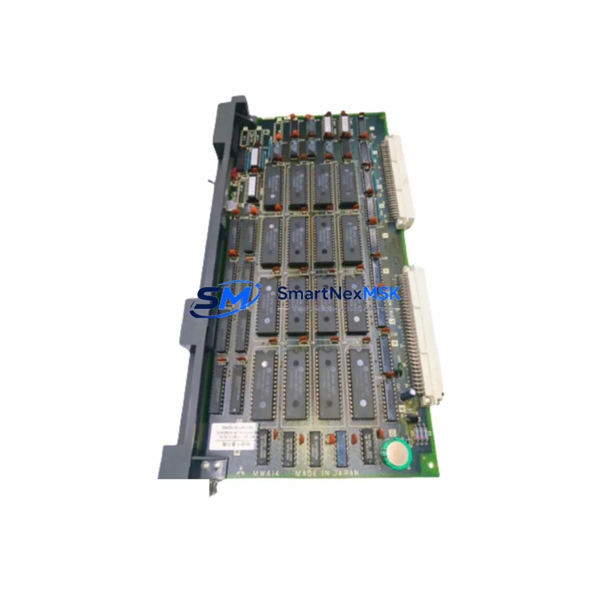
Mitsubishi MW414-MW414B Retrofit-Ready Power Supply for MELSEC-A Control Systems
The Mitsubishi Electric MW414 and MW414B are dedicated DC power supply modules engineered for the MELSEC-A Series programmable logic controller platform. As Mitsubishi Electric progressively phases out the MELSEC-A Series in favor of the MELSEC-Q and MELSEC-iQ-R platforms, the MW414 and MW414B have become critical retrofit components for facilities that must maintain operational continuity on legacy control systems without committing to a full platform migration. SMARTNEXMSK maintains verified stock of both variants, each tested prior to shipment and backed by a 12-month warranty.
The MW414B is the enhanced variant of the MW414, offering improved output stability and extended operating temperature tolerance — a distinction that matters in high-ambient-temperature environments such as foundries, chemical processing lines, and outdoor control cabinets. Both modules are designed to mount directly into the A-Series main base unit (A32B, A35B, A38B, A68B) and extension base units (A52B, A55B, A58B) without mechanical modification, preserving the original rack geometry and DIN rail footprint.
Upgrade Compatibility Table
| Parameter | MW414 | MW414B | Retrofit Notes |
|---|---|---|---|
| Input Voltage | 100–240 V AC | 100–240 V AC | Verify site supply voltage before installation |
| Output (5 VDC) | 6 A | 6 A | Confirm total I/O module current draw does not exceed rating |
| Base Unit Compatibility | A32B / A35B / A38B / A68B | A32B / A35B / A38B / A68B | Check slot position; power supply occupies leftmost slot |
| Extension Base Support | A52B / A55B / A58B | A52B / A55B / A58B | Extension cable (AC10B / AC30B) must be verified for continuity |
| Communication Compatibility | MELSEC-A native bus | MELSEC-A native bus | No protocol change required; A1SJ71UC24-R2 and A1SJ71E71-B2 remain compatible |
| Mounting | DIN rail / panel | DIN rail / panel | Direct drop-in; no bracket modification needed |
| Replacement Recommendation | Direct swap for failed MW414 | Preferred upgrade from MW414 in high-temp environments | MW414B recommended for new retrofit projects |
| Commissioning Focus | Verify 5 VDC output under load; check RUN LED status on A2ACPU / A3ACPU | Same as MW414; confirm READY output signal to CPU | Use GX Developer or GX Works2 for online monitoring during power-up |
| Warranty | 12 Months — Covered by SMARTNEXMSK | Includes pre-shipment load test and functional verification | |
Retrofit Planning for Existing Automation Systems
A successful MW414 or MW414B retrofit begins well before the module arrives on site. Engineers should start by auditing the total current consumption of all installed I/O modules across the main base and any extension bases. Common A-Series I/O modules such as the AX40, AX80, AY40, AY80, AD61, and DA62 each carry defined 5 VDC current requirements; the sum must remain within the power supply’s 6 A output ceiling. If the existing system has been expanded over the years with additional analog input modules (AD75P, AD71) or high-density digital I/O cards, a current budget recalculation is mandatory before energizing the replacement unit.
Terminal wiring on the MW414 and MW414B follows the standard MELSEC-A power terminal block layout: L, N, and PE for AC input, with the 5 VDC output distributed internally through the backplane connector. Installers should inspect the backplane connector pins on the base unit for oxidation or mechanical damage before seating the new module — a corroded backplane contact is a common root cause of intermittent power faults that are often misdiagnosed as CPU or I/O failures. The A2ACPU and A3ACPU CPU modules are particularly sensitive to supply voltage ripple; a clean, stable 5 VDC rail is essential for reliable program execution.
For systems that include the A1SJ71UC24-R2 serial communication module or the A1SJ71E71-B2 Ethernet interface module, no communication reconfiguration is required after a power supply swap — the MELSEC-A bus architecture isolates communication module addressing from the power supply slot. However, engineers should confirm that the communication module’s station number and baud rate parameters are preserved in the CPU’s program memory (flash or battery-backed RAM) before cycling power. If the A2ACPU or A3ACPU uses a memory cassette (A3NMCA-8 or similar), verify that the cassette is firmly seated and that the battery voltage is within specification before the retrofit to avoid program loss during the power interruption.
HMI panels connected via RS-232 or RS-422 to the A-Series CPU — including legacy GOT900 series terminals and third-party operator panels — will resume communication automatically after power restoration, provided the CPU program restarts in RUN mode. Confirm the CPU’s RUN/STOP switch position and the auto-start parameter in the system settings before the planned outage window. For facilities using SCADA systems connected through the A1SJ71E71-B2 Ethernet module, coordinate with the control room to suppress nuisance alarms during the brief power interruption.
Downtime Control During System Migration
Minimizing unplanned downtime during a power supply replacement on a MELSEC-A system requires a structured pre-outage checklist. First, use GX Developer or GX Works2 to perform a full program upload and save the ladder logic, parameter files, and device comments to a secure engineering workstation — never rely solely on the CPU’s internal memory as the sole backup. If the system uses the A3ACPU with extended memory, verify that the backup includes all file registers (D, W) and special relay states that the process depends on.
Schedule the replacement during a planned maintenance window and communicate the expected outage duration to operations. A straightforward MW414 or MW414B swap — assuming no backplane damage and no wiring changes — typically requires 15 to 30 minutes from power-down to verified RUN status. Prepare a commissioning checklist that covers: (1) visual inspection of the new module and backplane connector, (2) seating and securing the module latch, (3) applying AC power and verifying the POWER LED illuminates, (4) confirming the CPU transitions to RUN mode and the RUN LED is steady, (5) checking all I/O module status LEDs for normal indication, and (6) verifying communication link status on any installed A1SJ71UC24-R2 or A1SJ71E71-B2 modules.
For critical processes where even a 30-minute outage is unacceptable, consider maintaining a pre-tested hot-spare MW414B on the shelf. SMARTNEXMSK can supply pre-tested units with a functional verification report, reducing the on-site commissioning risk and supporting your spare-parts inventory strategy. All units ship with a 12-month warranty and are available for express dispatch to minimize lead time in emergency breakdown scenarios.
Retrofit Support FAQ
Q1: Is the MW414B a direct drop-in replacement for the MW414, or are there wiring differences?
The MW414B is electrically and mechanically compatible with the MW414 in all standard MELSEC-A base units (A32B, A35B, A38B, A68B). The terminal block layout and backplane connector are identical. No wiring changes are required. The MW414B offers improved output stability and is the recommended choice for new retrofit projects or high-temperature environments.
Q2: How do I verify the replacement unit is functioning correctly after installation?
After seating the module and applying AC power, confirm the POWER LED on the MW414/MW414B illuminates steadily. Then verify the CPU (A2ACPU or A3ACPU) transitions to RUN mode with the RUN LED steady. Use GX Developer or GX Works2 to perform an online connection and confirm the program is executing. Check all I/O module status LEDs and verify that field devices are responding as expected. SMARTNEXMSK performs a pre-shipment load test on every unit; a functional verification report is available on request.
Q3: What should I check if the CPU does not enter RUN mode after replacing the power supply?
First, confirm the CPU RUN/STOP switch is in the RUN position. Check that the memory cassette (if fitted) is firmly seated and the battery is not depleted. Verify that the total current draw of all installed I/O modules does not exceed the 6 A output rating of the MW414/MW414B. Inspect the backplane connector on the base unit for bent pins or oxidation. If the CPU displays an error code, refer to the MELSEC-A CPU error code table in the hardware manual for diagnosis.
Q4: Does SMARTNEXMSK offer a warranty on the MW414 and MW414B, and what does it cover?
Yes. All MW414 and MW414B units supplied by SMARTNEXMSK are covered by a 12-month warranty from the date of shipment. The warranty covers manufacturing defects and functional failures under normal operating conditions. Each unit undergoes a pre-shipment functional test including output voltage verification under load. In the event of a warranty claim, SMARTNEXMSK will arrange replacement or repair. Contact sales@smartnexmsk.com or +86 18259474341 for warranty support.
© 2026 SMARTNEXMSK. All rights reserved.
Original Source: https://smartnexmsk.com
Contact: sales@smartnexmsk.com | +86 18259474341