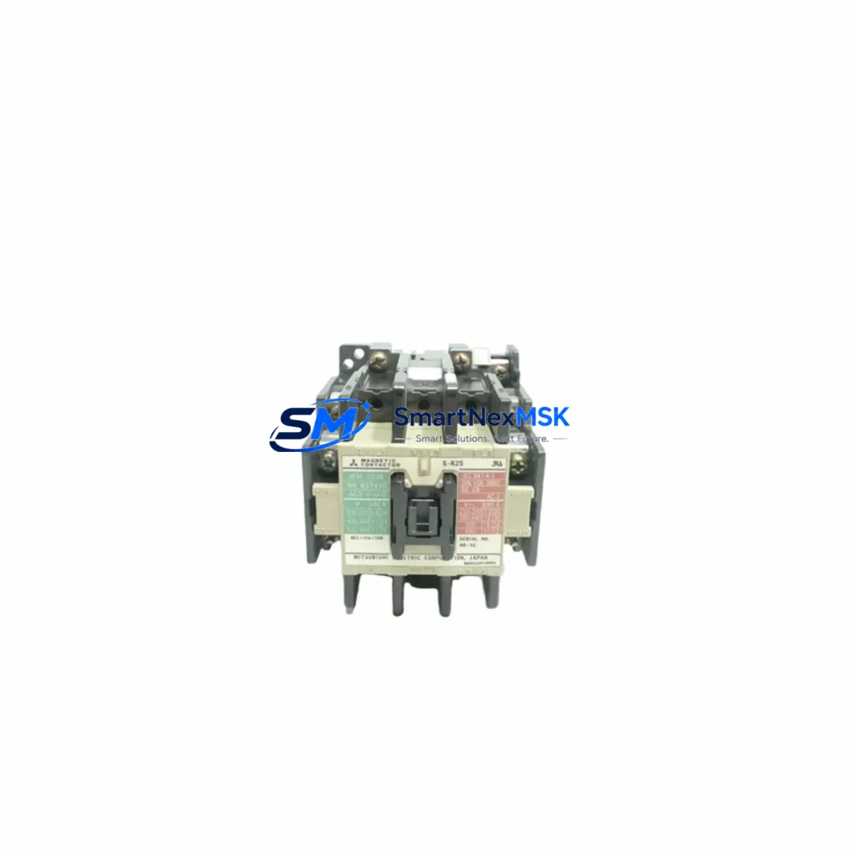
Mitsubishi S-K25 Retrofit-Ready AC Contactor for S-K Series Control Systems
The Mitsubishi Electric S-K25 is a 25A, 3-pole AC magnetic contactor engineered for seamless integration into legacy and modern S-K Series motor control and power switching applications. As industrial facilities face increasing pressure to modernize aging control infrastructure without full system overhauls, the S-K25 stands out as a proven retrofit-ready solution — offering drop-in dimensional compatibility, verified coil voltage options, and reliable auxiliary contact configurations that align with the original S-K Series design standard.
Whether you are replacing a failed unit on an active production line, upgrading a control cabinet that has been running legacy Mitsubishi contactors for over a decade, or migrating from an obsolete model such as the S-K21 or S-K18 to a current-production component, the S-K25 delivers the electrical and mechanical continuity your system demands. Its compact footprint fits standard DIN rail and panel-mount configurations used across S-K Series motor control centers, making it a preferred choice for maintenance engineers who need to minimize downtime and avoid costly rewiring.
Upgrade Compatibility Table
| Parameter | S-K25 Specification | Retrofit Notes |
|---|---|---|
| Rated Current | 25A (AC-3) | Verify load current matches; suitable for motors up to 11kW/400V |
| Pole Configuration | 3-Pole Main + Auxiliary | Auxiliary contact (1NO+1NC) matches S-K Series standard wiring |
| Coil Voltage Options | AC 100V / 200V / 220V / 380V / 440V | Confirm coil voltage against existing control circuit before ordering |
| Mounting | DIN Rail / Panel Mount | Drop-in fit for existing S-K Series panel cutouts and rail positions |
| Terminal Compatibility | Screw terminals, standard pitch | Existing wire gauges and lug types are compatible; no re-termination required |
| Communication / Control | Hardwired coil control | Compatible with PLC digital output modules (e.g., Mitsubishi Q series DO cards) |
| Replacement Models | S-K21, S-K18, S-K12 (legacy) | Verify auxiliary contact count if replacing S-K12 in multi-contact schemes |
| Warranty | 12 Months | Covers manufacturing defects; includes pre-shipment functional test |
Retrofit Planning for Existing Automation Systems
Successful integration of the S-K25 into an existing control system requires a structured pre-installation review. Begin by auditing the control cabinet layout to confirm available rail space and verify that the existing Mitsubishi S-K Series thermal overload relay — typically an TH-K Series overload relay such as the TH-K20 or TH-K60 — is rated for the S-K25’s frame and terminal interface. The S-K25 is designed to couple directly with compatible TH-K overload relays without adapter brackets, preserving the original wiring topology.
Next, review the PLC output wiring. In systems controlled by a Mitsubishi MELSEC Q Series or iQ-R Series PLC, the contactor coil is typically driven by a QY40P or RY40PT5P transistor output module. Confirm that the output module’s rated load current and voltage match the S-K25 coil specifications. If the existing system uses relay output modules such as the QY10 or RY10R, no additional interface relay is required — the S-K25 coil can be driven directly.
For systems that include a GOT2000 Series HMI (e.g., GT2710-VTBA) with motor status monitoring screens, verify that the auxiliary contact feedback wiring from the S-K25 is routed to the correct PLC input module — typically a QX40 or RX40C7 digital input card. This ensures that the HMI motor run/stop status display remains accurate after the contactor swap without requiring any ladder logic or screen modifications.
In control cabinets where the S-K25 is part of a star-delta starter circuit, also inspect the companion contactors — typically an S-K12 for the star contactor and an S-K25 or S-K35 for the delta contactor — to ensure interlock wiring and timing relay settings (e.g., on an Anywire or Mitsubishi timer relay) remain unchanged. The S-K25’s auxiliary contact block layout supports direct interlock wiring without rewiring the interlock circuit.
Power supply verification is equally critical. Confirm that the control transformer or MELSEC PS-series power supply module feeding the coil circuit can sustain the S-K25 inrush current during energization. In multi-contactor panels, cumulative coil inrush can stress undersized transformers — a common oversight during retrofit projects that leads to nuisance tripping of the control circuit breaker.
Downtime Control During System Migration
Minimizing production downtime during a contactor replacement requires preparation before the maintenance window begins. Pre-stage the S-K25 unit with the correct coil voltage installed and auxiliary contact block verified. Label all existing wires on the S-K Series contactor being removed using numbered ferrules before disconnecting any terminals — this eliminates reconnection errors and accelerates the swap.
Back up the PLC program from the Mitsubishi MELSEC controller using GX Works3 or GX Works2 before beginning any work. Even though a contactor swap does not alter the PLC program, having a verified backup protects against accidental parameter loss if the CPU is powered down during the cabinet work. Store the backup on a CF card or USB memory module connected to the CPU.
During the swap, maintain control circuit continuity where possible by isolating only the affected motor branch circuit rather than shutting down the entire MCC. Use the appropriate lockout/tagout procedure for the motor branch, while keeping the PLC CPU and HMI powered. This allows other production lines sharing the same controller to continue operating.
After installation, perform a functional test sequence: energize the S-K25 coil from the PLC output, verify main contact closure with a continuity tester across the load terminals, confirm auxiliary contact state change is reflected on the HMI status screen, and run the motor under no-load conditions before returning to full production. Total swap time for a prepared technician is typically under 30 minutes per contactor position.
Retrofit Support FAQ
Q: Is the S-K25 a direct drop-in replacement for the S-K21?
A: Yes. The S-K25 shares the same mounting footprint, terminal pitch, and auxiliary contact interface as the S-K21. The primary difference is the higher rated current (25A vs. 21A AC-3), which provides additional thermal margin in applications where the S-K21 was operating near its rated capacity. No wiring changes are required.
Q: What coil voltage should I order for my existing control circuit?
A: Check the nameplate of the contactor being replaced or trace the control wiring to the control transformer secondary. Common coil voltages in S-K Series installations are AC 200V (50/60Hz) for domestic Japanese systems and AC 220V or 380V for export and international installations. Specify the coil voltage at the time of order — incorrect coil voltage is the most common cause of installation delays.
Q: Does the S-K25 require any PLC program changes after installation?
A: No program changes are required for a like-for-like replacement. The S-K25 auxiliary contact outputs (1NO+1NC) map directly to the existing PLC input wiring. If you are upgrading from a model with a different auxiliary contact count (e.g., S-K12 with only 1NO), verify that all required feedback signals are available and add an auxiliary contact block if needed before finalizing the installation.
Q: What does the 12-month warranty cover, and is pre-shipment testing performed?
A: Every S-K25 unit is functionally tested prior to shipment, including coil energization verification, main contact resistance measurement, and auxiliary contact continuity check. The 12-month warranty covers manufacturing defects in materials and workmanship from the date of shipment. Units showing signs of incorrect installation voltage, mechanical damage from mishandling, or unauthorized modification are excluded from warranty coverage. Contact sales@smartnexmsk.com for warranty claims and RMA processing.
© 2026 SMARTNEXMSK. All rights reserved.
Original Source: https://smartnexmsk.com
Contact: sales@smartnexmsk.com | +86 18259474341