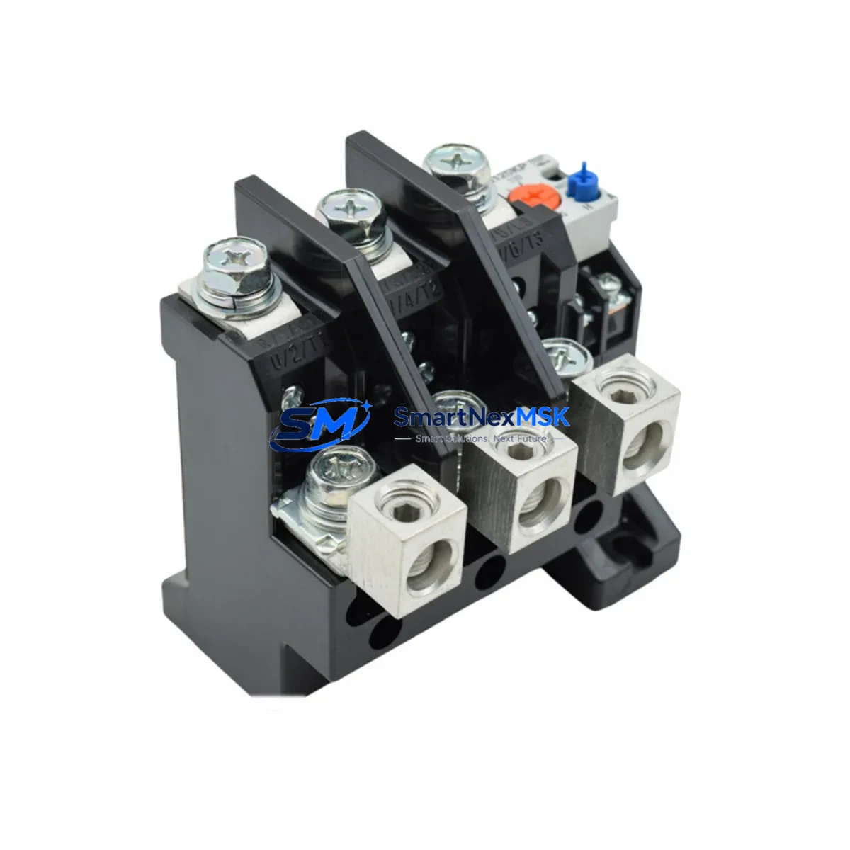
Mitsubishi TH-N12KP Spare for TH-N Series Automation
The Mitsubishi TH-N12KP is a bimetallic thermal overload relay engineered for the TH-N series lineup, designed to provide reliable motor protection in industrial control panels, machine tool cabinets, and process automation systems. As a maintenance-ready original spare, the TH-N12KP covers a current setting range of 7–12 A and is built to mount directly onto Mitsubishi S-N series magnetic contactors — including the S-N10, S-N12, and S-N18 — without additional adapters or wiring modifications. For maintenance engineers managing aging MELSEC or FR-series drive systems, stocking the TH-N12KP as a certified replacement eliminates unplanned downtime caused by nuisance tripping or relay failure during peak production cycles.
Every unit supplied by SMARTNEXMSK is sourced from authorized distribution channels, individually inspected, and tested for trip-class accuracy and reset function before shipment. A 12-month warranty covers all units against manufacturing defects, giving procurement engineers confidence in long-term spare parts planning.
Spare Maintenance Table
| Parameter | Specification |
|---|---|
| Model / SKU | TH-N12KP |
| Brand | Mitsubishi Electric |
| Series | TH-N Series |
| Product Type | Thermal Overload Relay |
| Current Setting Range | 7 – 12 A |
| Trip Class | Class 10 (IEC 60947-4-1) |
| Compatible Contactors | S-N10, S-N12, S-N18 (Mitsubishi S-N Series) |
| Reset Mode | Manual / Automatic (field-selectable) |
| Phase Loss Sensitivity | Yes |
| Ambient Temperature | -10°C to +60°C |
| Installation | Direct contactor mount, DIN rail compatible |
| Origin | Japan |
| Warranty | 12 Months |
| Pre-shipment Testing | Yes — trip accuracy and reset function verified |
| Typical Application | Motor protection, conveyor drives, pump control panels |
Maintenance Planning for Continuous Operation
When a TH-N12KP trips or shows signs of calibration drift — evidenced by nuisance tripping below the rated current or failure to trip under sustained overload — the replacement procedure should be treated as a full thermal protection audit of the affected motor branch circuit. Maintenance engineers should not limit the inspection to the relay itself. The associated S-N10 or S-N12 contactor should be checked for contact wear, arc erosion on the main poles, and coil voltage integrity. If the contactor coil is drawing abnormal current, the upstream control transformer or 24 VDC power supply module feeding the control circuit should be verified for output stability.
In MELSEC Q-series or iQ-R series PLC panels where the TH-N12KP is wired into a digital input module for remote trip monitoring, the I/O wiring continuity and terminal block torque should be confirmed during the same maintenance window. Loose terminal connections on the 95/96 auxiliary contact output are a common source of false trip signals in SCADA systems. If the panel includes a Mitsubishi FR-E700 or FR-D700 series inverter drive on the same motor branch, the drive’s electronic thermal protection settings should be cross-checked against the relay’s current setting to avoid conflicting protection thresholds.
For control cabinets running legacy systems, it is advisable to simultaneously inspect the fuse holders and NH-type fuse links on the motor feeder, the PE terminal blocks and grounding bus integrity, and any signal isolators or relay output modules used to interface the overload trip signal with a DCS or safety PLC. Where the panel includes a GOT2000 series HMI, the alarm history log should be reviewed to identify recurring trip patterns that may indicate motor insulation degradation rather than relay fault. Stocking the TH-N12KP alongside compatible S-N series contactors, control power fuses, and auxiliary contact blocks as a coordinated spare kit significantly reduces mean time to repair (MTTR) during unplanned shutdowns.
Site Replacement Workflow
Step 1 — Isolation and Lockout: De-energize the motor branch circuit at the upstream MCCB or isolator. Apply LOTO (Lockout/Tagout) per site safety procedure. Confirm zero voltage at the contactor line terminals using a calibrated multimeter.
Step 2 — Document Current Settings: Record the existing TH-N12KP current dial setting before removal. Photograph the wiring layout at the 95/96 auxiliary contact terminals and the T1/T2/T3 load-side terminals for reference during reinstallation.
Step 3 — Remove the Faulty Relay: Disconnect the auxiliary contact wiring. Release the relay from the contactor by pressing the mounting latch and sliding the unit free. Inspect the contactor’s relay mounting interface for damage or carbon deposits.
Step 4 — Install TH-N12KP Replacement: Slide the new TH-N12KP onto the S-N series contactor until the latch clicks. Reconnect auxiliary contact wiring to terminals 95/96 (NC) and 97/98 (NO) as per the original wiring diagram. Set the current dial to the motor’s rated full-load current (FLA) as shown on the motor nameplate.
Step 5 — Functional Test: Re-energize the circuit and perform a no-load test run. Verify the relay does not trip under normal starting current. Confirm the remote trip signal is correctly received at the PLC input module or SCADA system. Log the replacement in the maintenance management system (CMMS) with the new unit’s serial number and installation date.
This workflow is compatible with direct replacement of legacy TH-N12 (non-KP) units in existing S-N contactor assemblies. The KP suffix denotes the phase-loss sensitivity feature, which provides enhanced protection for three-phase motor circuits and is recommended for all new installations and upgrades.
Spare Parts Support FAQ
Q1: Is the TH-N12KP a direct replacement for the TH-N12 in existing S-N contactor assemblies?
Yes. The TH-N12KP is dimensionally and electrically compatible with the TH-N12 and mounts directly onto S-N10, S-N12, and S-N18 contactors. The KP variant adds phase-loss sensitivity, which is a functional upgrade and does not require any wiring changes.
Q2: How is the unit tested before shipment?
Every TH-N12KP unit is individually tested for trip-class accuracy across the full current setting range and for correct manual and automatic reset operation. Units that do not meet Mitsubishi Electric’s published specifications are not shipped. A test record is available upon request for critical infrastructure procurement.
Q3: What is the recommended spare parts stocking strategy for the TH-N12KP?
For facilities operating more than three motors protected by TH-N series relays, a minimum stock of two TH-N12KP units per current range in use is recommended. Given the relay’s role as a primary motor protection device, a stockout during an unplanned failure can result in extended downtime. SMARTNEXMSK supports blanket purchase orders and scheduled replenishment for MRO procurement teams.
Q4: What does the 12-month warranty cover?
The 12-month warranty covers manufacturing defects, calibration failures, and premature trip mechanism failure under normal operating conditions. It does not cover damage caused by installation errors, overcurrent events beyond the relay’s rated capacity, or environmental exposure outside the specified ambient temperature range. Warranty claims are processed with a replacement unit dispatched within 5 business days of fault confirmation.
© 2026 SMARTNEXMSK. All rights reserved.
Original Source: https://smartnexmsk.com
Contact: sales@smartnexmsk.com | +86 18259474341