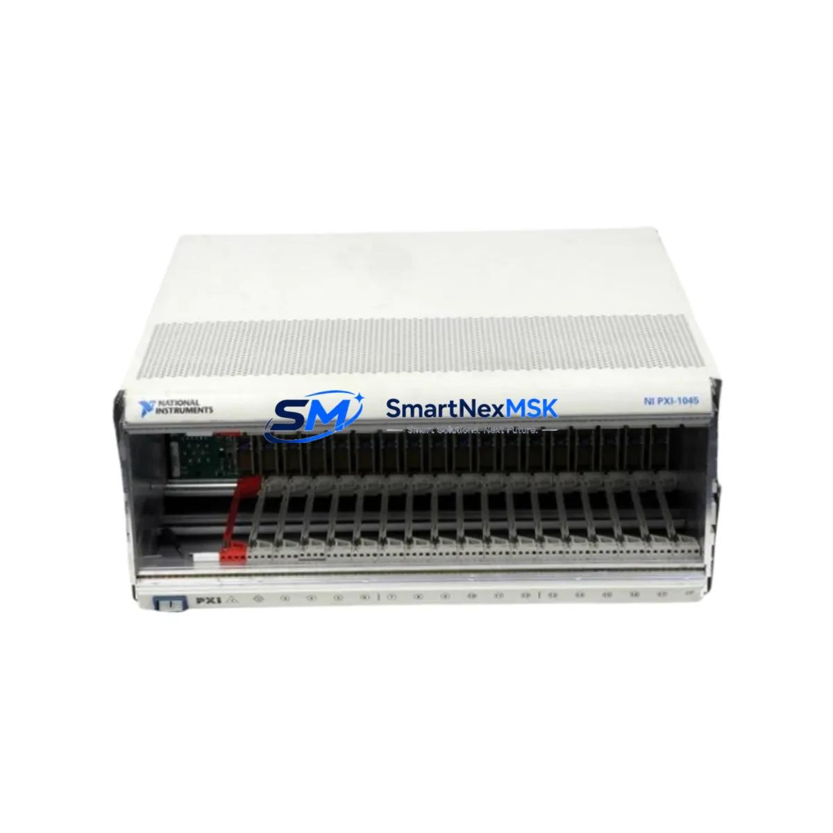
NI PXI-1045 Retrofit-Ready 18-Slot Chassis for PXI Series Control Systems
The NI PXI-1045 is an 18-slot PXI chassis engineered for high-density instrumentation and industrial control applications. As legacy PXI platforms reach end-of-life, the PXI-1045 has become a critical retrofit component for engineers tasked with modernizing aging test and measurement infrastructure without full system replacement. Whether you are migrating from an earlier NI PXI-1042 or NI PXI-1033 chassis, or expanding an existing rack to accommodate additional I/O modules, the PXI-1045 provides a proven, backward-compatible upgrade path that preserves your existing software investment and minimizes production downtime.
Designed to accept standard 3U PXI and CompactPCI modules, the PXI-1045 supports a wide range of NI instrumentation cards including digitizers, function generators, digital multimeters, and high-speed data acquisition modules. Its integrated timing and synchronization backplane makes it fully compatible with NI PXI-6653 timing modules and PXI-6682 GPS synchronization cards, enabling precise multi-chassis triggering in complex test environments. The chassis delivers up to 400 W of system power, accommodating power-hungry modules such as the NI PXI-5922 flexible-resolution digitizer and NI PXI-4110 programmable DC power supply without thermal derating.
For retrofit projects, engineers must verify several critical parameters before commissioning the PXI-1045 as a replacement unit. Power capacity planning is essential: calculate the aggregate power draw of all installed modules against the chassis power budget, accounting for inrush current during startup. Terminal and backplane interface compatibility should be confirmed for each slot assignment, particularly when migrating from a chassis with a different slot count or star trigger topology. Module address configuration in NI MAX (Measurement & Automation Explorer) must be updated to reflect the new chassis resource name, and any LabVIEW or TestStand sequences referencing the old chassis alias will require a resource remapping step before execution.
Communication link integrity is another key checkpoint. If your system relies on MXI-Express connectivity—using an NI PXI-8374 MXI-Express module paired with a host PC—verify that the MXI cable length and topology remain within specification after the chassis swap. For systems using PXI-8232 Ethernet interface modules or PXI-8430 serial interface cards, confirm that IP address assignments and COM port mappings are preserved in the Windows Device Manager after the chassis is powered on for the first time.
Upgrade Compatibility Table
| Parameter | NI PXI-1045 (This Unit) | NI PXI-1042 (Legacy) | Notes |
|---|---|---|---|
| Slot Count | 18 slots | 8 slots | Expanded I/O capacity; re-address all modules in NI MAX |
| System Controller Slot | Slot 1 (dedicated) | Slot 1 (dedicated) | Compatible with NI PXI-8108 and PXI-8110 embedded controllers |
| Backplane Interface | PXI / CompactPCI | PXI / CompactPCI | Full backward compatibility with 3U PXI modules |
| Power Supply | 400 W | 200 W | Verify module power budget before migration |
| Timing & Sync | 10 MHz reference, PXI_TRIG[0:7] | 10 MHz reference, PXI_TRIG[0:7] | Compatible with NI PXI-6653 timing modules |
| Communication Compatibility | MXI-Express, Ethernet, Serial | MXI-4, Ethernet | MXI-Express upgrade may require NI PXI-8374 host adapter |
| Cooling | Forced-air, front-to-back | Forced-air, front-to-back | Ensure rack airflow clearance ≥ 1U above and below chassis |
| Installation Format | 19-inch rack mount | 19-inch rack mount | Standard EIA rack; verify rail depth compatibility |
| Commissioning Requirement | NI MAX resource remap required | — | Update chassis alias and slot assignments in LabVIEW project |
| Warranty | 12-Month Warranty Included | Covers hardware defects; functional test report available on request | |
Retrofit Planning for Existing Automation Systems
A successful PXI-1045 retrofit begins with a thorough audit of the existing control cabinet and rack layout. Start by documenting every module currently installed in the legacy chassis—including NI PXI-6251 multifunction DAQ cards, NI PXI-2530 switching modules, NI PXI-4070 digital multimeters, and any NI PXI-8430/8 serial interface cards—along with their slot positions, resource names, and wiring terminations. This inventory forms the baseline for your migration checklist and ensures no I/O channel is left unmapped after the swap.
Terminal block and cable assembly compatibility deserves particular attention. Many legacy installations use NI SH68-68-EP shielded cables and TBX-68 terminal blocks for analog I/O connections. These accessories are fully compatible with the PXI-1045 when paired with the same DAQ modules, so existing field wiring can typically be preserved without modification. However, if the retrofit involves upgrading from older NI PXI-6025E DAQ cards to newer NI PXI-6255 high-channel-count modules, the connector pinout changes and new cable assemblies will be required.
For systems incorporating HMI panels—such as NI TouchPanel computers or third-party SCADA displays communicating over Modbus TCP or OPC-UA—verify that the HMI screen tag database references the correct PLC or DAQ resource addresses after the chassis migration. If the control architecture includes an NI PXI-8108 embedded controller running LabVIEW Real-Time, the RT target IP address and project reference must be updated in the LabVIEW development environment before redeployment. Similarly, any NI PXI-8232 Gigabit Ethernet modules used for deterministic data streaming should be reconfigured in NI Distributed System Manager to reflect the new chassis topology.
Rack space and power distribution planning should not be overlooked. The PXI-1045 occupies 4U of rack height and requires a dedicated 20 A circuit at 100–240 VAC. If the existing control cabinet uses a shared power distribution unit, confirm that the available amperage headroom is sufficient before energizing the new chassis. Grounding continuity between the chassis frame and the cabinet earth bus must also be verified per IEC 61010-1 safety requirements.
Downtime Control During System Migration
Minimizing production downtime during a PXI chassis migration requires a structured hot-swap strategy and thorough pre-staging. Before the maintenance window opens, pre-configure the NI PXI-1045 on a bench: install all modules in their designated slots, assign resource names in NI MAX, and load the application software onto the embedded controller or host PC. Run a full functional verification—including channel-by-channel I/O checks and communication link tests—before the chassis is transported to the production floor.
During the cutover, follow a module-by-module transfer sequence rather than removing all cards simultaneously. This approach allows you to maintain partial system functionality and quickly identify any slot-specific issues before committing to a full migration. Keep the original chassis powered and accessible as a fallback reference until the new system has completed its first full production cycle without fault.
Program logic preservation is critical. Export all LabVIEW project files, TestStand sequences, and NI MAX configuration exports (*.nce files) to a version-controlled repository before the migration begins. If the system uses NI VeriStand for real-time testing, export the system definition file and verify that all channel mappings resolve correctly against the new chassis resource names. For installations where the PXI controller interfaces with a Siemens S7 or Allen-Bradley ControlLogix PLC via OPC-UA, confirm that the OPC server tag paths remain valid after the chassis IP address is updated.
Post-migration, conduct a structured commissioning sequence: power on the chassis, verify all module LEDs indicate normal status, confirm communication links are established, and execute a representative subset of the production test sequence before releasing the line. Document the commissioning results and retain them alongside the 12-month warranty certificate for audit traceability.
Retrofit Support FAQ
Q1: Is the NI PXI-1045 a direct drop-in replacement for the NI PXI-1042 or NI PXI-1033?
The PXI-1045 is mechanically and electrically compatible with all standard 3U PXI and CompactPCI modules used in the PXI-1042 and PXI-1033. However, because the slot count differs, module resource addresses in NI MAX must be remapped, and any software references to the old chassis alias must be updated. No hardware modification to the modules themselves is required.
Q2: What commissioning steps are required after installing the PXI-1045?
After physical installation, open NI MAX and confirm the chassis appears under “Devices and Interfaces.” Assign a chassis alias, verify each module’s resource name, and run a self-test on all installed devices. Update your LabVIEW or TestStand project to reference the new resource names, then execute a channel verification routine to confirm all I/O signals are within expected ranges before returning the system to production.
Q3: Can existing field wiring and terminal blocks be reused with the PXI-1045?
In most cases, yes. If the same DAQ or switching modules are being transferred from the old chassis to the PXI-1045, the existing cable assemblies and terminal blocks remain compatible. Wiring changes are only necessary if the module type is also being upgraded (e.g., replacing a PXI-6025E with a PXI-6255), which may involve a different connector type or pinout.
Q4: What does the 12-month warranty cover, and is a functional test report available?
The 12-month warranty covers all hardware defects in materials and workmanship under normal operating conditions. Each unit undergoes a pre-shipment functional test including power-on verification, backplane integrity check, and slot communication test. A functional test report is available upon request and can be provided with the shipment documentation for incoming inspection and quality records.
© 2026 SMARTNEXMSK. All rights reserved.
Original Source: https://smartnexmsk.com
Contact: sales@smartnexmsk.com | +86 18259474341