Omron 57C404B 57C424 Spare for C Series Automation: Spare Replacement & Industrial Downtime Risk Control
The Omron 57C404B / 57C424 is an original analog output module designed for the Omron C Series PLC platform — one of the most widely deployed programmable logic controller families in industrial automation. As a maintenance-ready spare, this unit is sourced, inspected, and tested prior to shipment to ensure immediate drop-in compatibility with existing C Series control architectures. Whether you are managing a planned shutdown, responding to an unscheduled fault, or building a strategic spare parts inventory, the 57C404B/57C424 provides the signal output reliability your process demands.
Spare Maintenance Table
| Parameter | Specification |
|---|---|
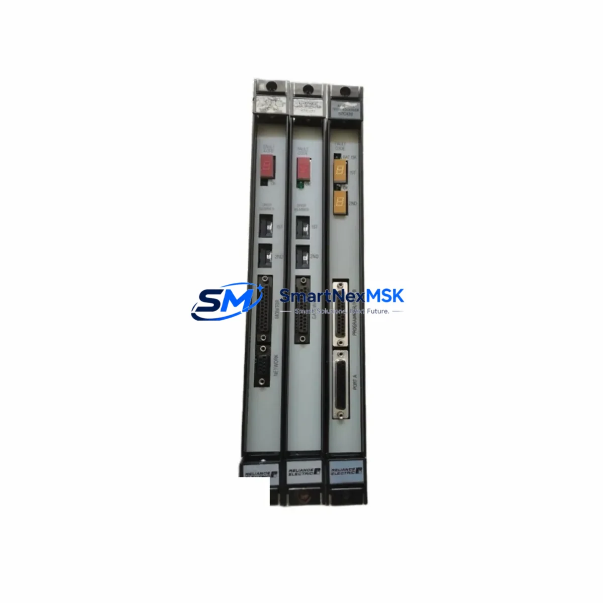
| SKU / Part Number | 57C404B / 57C424 |
| Brand | Omron |
| Series | C Series PLC |
| Module Type | Analog Output Module |
| Output Channels | 4-channel analog output (inferred from SKU series) |
| Output Signal | 4–20 mA / 0–10 V DC (C Series standard) |
| Power Supply | 5 VDC via backplane (C Series rack) |
| Mounting | C Series I/O rack / backplane slot |
| Operating Temperature | 0–55°C (standard industrial range) |
| Origin | Japan |
| Compatibility | Omron C Series PLC racks; cross-compatible with 57C424 variant |
| Condition | Original, tested before shipment |
| Warranty | 12 Months |
| Delivery | Worldwide express shipping available |
Maintenance Planning for Continuous Operation
When a C Series analog output module such as the 57C404B fails or degrades, the fault rarely exists in isolation. Experienced maintenance engineers know that analog signal drift, output saturation, or complete channel failure often points to stress across the entire I/O subsystem. A thorough site inspection should accompany any module replacement.
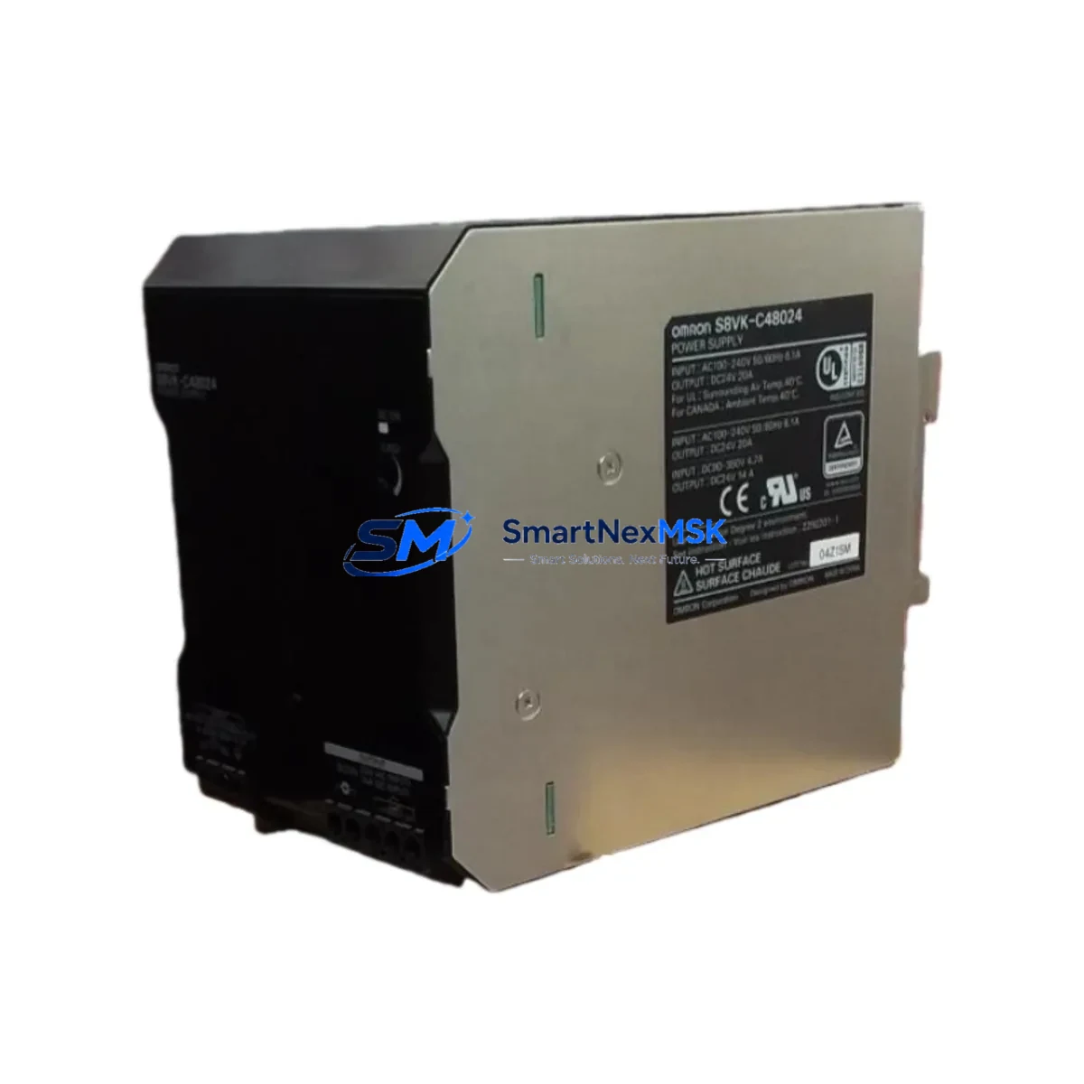
Begin by verifying the C Series power supply module — units such as the C200H-PA204 or equivalent rack power supply — to confirm stable 5 VDC and 24 VDC rail voltages. Voltage sag or ripple on the backplane can accelerate analog module failure and cause erratic output behavior. Simultaneously, inspect the C Series CPU module (e.g., C200H-CPU31 or C200HE-CPU42) for firmware integrity and scan-cycle anomalies that may have contributed to the output fault.
Check the C Series backplane or I/O rack for oxidized slot contacts, which are a common cause of intermittent analog channel errors in aging systems. If the control cabinet has been in service for more than five years, it is advisable to inspect the terminal block assemblies and field wiring connected to the analog output channels — loose terminations or corroded conductors can introduce signal noise that damages output DAC circuits over time.
For systems using signal isolators between the PLC analog output and field instruments (transmitters, control valves, or variable-frequency drives), verify that the isolators — such as loop-powered 4–20 mA signal conditioners — are functioning within specification. A failed isolator can back-feed voltage into the module output circuit and cause premature failure of the replacement unit.
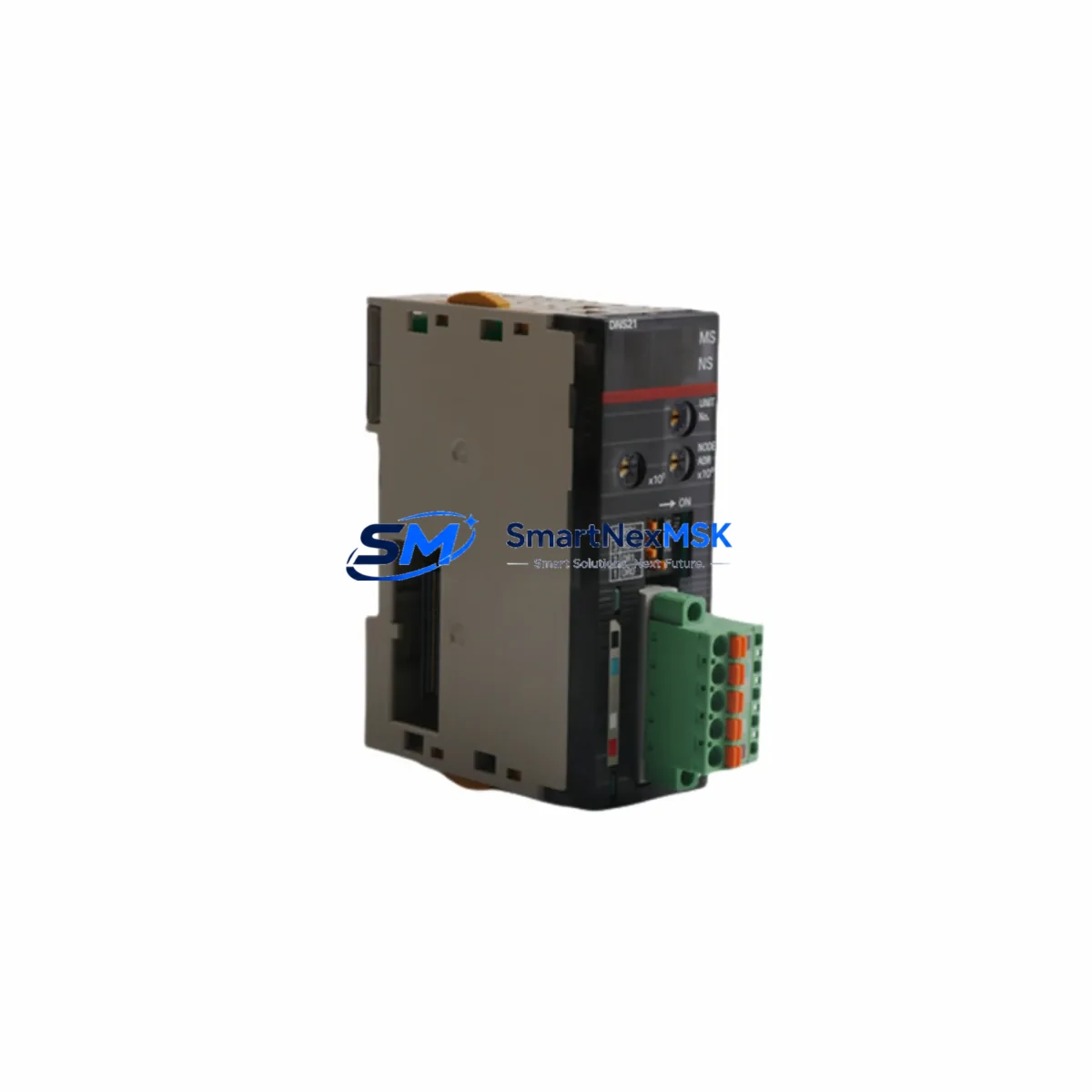
If the C Series system communicates via Omron Host Link (C-mode) or SYSMAC NET, inspect the communications module (e.g., C200H-LK201) for error flags that may indicate upstream data integrity issues affecting analog setpoint delivery. In multi-drop RS-485 configurations, a faulty termination resistor or damaged cable shield can introduce noise that manifests as analog output instability.
For cabinets with relay output modules (e.g., C200H-OC225) controlling solenoids or contactors in the same enclosure, check for coil suppression diodes — inductive switching transients are a leading cause of analog module degradation in mixed I/O cabinets. Additionally, inspect any fuse holders or circuit protection on the 24 VDC field supply rail; a partially blown fuse can cause intermittent analog output errors that are difficult to diagnose without a systematic inspection.
Finally, if an HMI panel (such as an Omron NT-series or third-party operator terminal) is connected to the C Series CPU, verify that the HMI communication cable and port are intact — a communication fault at the HMI level can sometimes be misdiagnosed as an analog output module failure when the root cause is a corrupted setpoint register.
Site Replacement Workflow
Step 1 — Isolation: Place the C Series CPU in STOP mode via the keyswitch or programming console. Confirm all analog output channels are at zero or safe state before removing the module.
Step 2 — Documentation: Record the slot address, I/O table allocation, and any DIP switch or jumper settings on the outgoing 57C404B/57C424 module. Photograph the wiring terminations before disconnection.
Step 3 — Module Swap: Remove the faulty module from the C Series rack. Insert the replacement 57C404B/57C424 into the same slot. Confirm the backplane connector is fully seated and the module latch is engaged.
Step 4 — Wiring Restoration: Reconnect field wiring to the terminal block in the original configuration. Verify wire gauge and termination torque per Omron installation guidelines.
Step 5 — I/O Table Verification: Using CX-Programmer or SYSMAC Support Software, confirm the I/O table recognizes the replacement module in the correct slot with the correct unit number assignment.
Step 6 — Functional Test: Return the CPU to RUN mode. Command each analog output channel to a known setpoint and verify the field instrument response with a calibrated loop calibrator or multimeter. Confirm all four channels are within specification before releasing the system to production.
This workflow minimizes downtime, eliminates configuration errors, and ensures the replacement module is validated before the process resumes — reducing the risk of a repeat fault event.
Spare Parts Support FAQ
Q1: Is the 57C404B directly interchangeable with the 57C424?
Based on Omron C Series documentation and industry maintenance records, the 57C404B and 57C424 are closely related analog output variants within the same C Series module family. Both are compatible with standard C Series I/O racks. Confirm slot addressing and DIP switch configuration before installation to ensure full functional equivalence in your specific system revision.
Q2: What pre-shipment testing is performed on this spare?
Each unit undergoes functional verification prior to dispatch, including power-on testing and output channel continuity checks. Units are shipped with protective packaging to prevent ESD damage and physical shock during transit. A 12-month warranty covers manufacturing defects and functional failures under normal operating conditions.
Q3: How should I manage C Series analog output modules in my spare parts inventory?
For facilities running C Series PLCs in critical process applications, it is recommended to maintain at least one spare 57C404B/57C424 per control system. Store spares in anti-static bags in a climate-controlled environment (10–40°C, <75% RH). Rotate stock every 3–5 years to prevent capacitor aging. Label each spare with the system it is designated for to accelerate emergency response.
Q4: Can this module be used to extend the life of an aging C Series system?
Yes. The 57C404B/57C424 is a direct original-specification replacement that allows aging C Series installations to continue operating without a full system migration. Combined with a systematic inspection of associated power, I/O, and communication components, replacing worn analog output modules is a cost-effective strategy for extending system life by 5–10 years while deferring capital expenditure on new PLC platforms.
© 2026 SMARTNEXMSK. All rights reserved.
Original Source: https://smartnexmsk.com
Contact: sales@smartnexmsk.com | +86 18259474341