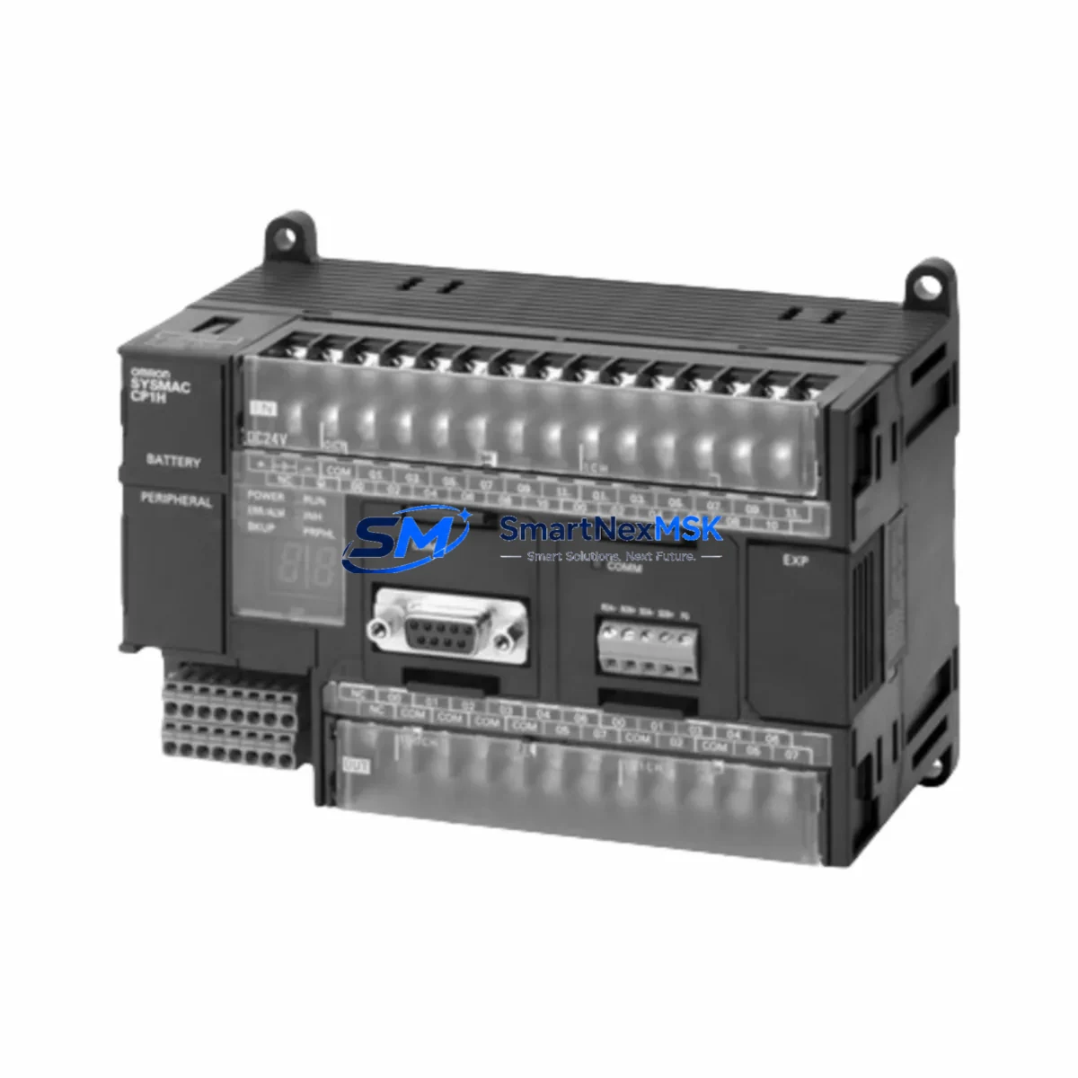
OMRON CP1H-X40DR-A Retrofit-Ready Relay Output PLC for CP1H Series Control Systems
The OMRON CP1H-X40DR-A is a 40-point relay output programmable logic controller engineered for seamless integration into existing CP1H Series automation architectures. Whether you are replacing a failed unit on an active production line, upgrading an aging control cabinet, or migrating from an earlier OMRON C200H or CPM2A platform, the CP1H-X40DR-A delivers the I/O density, instruction set compatibility, and communication flexibility required for a controlled, low-risk retrofit.
This unit supports 24 DC inputs and 16 relay outputs, operates on a 100–240 VAC power supply, and is fully compatible with the CX-Programmer software environment used across the CP1H, CP1L, and CJ1M product families. Its onboard USB programming port and optional RS-232C/RS-422A serial expansion make it a practical drop-in for legacy systems that previously relied on the CP1H-X40DT-D or CP1H-X40DT1-D transistor output variants, where relay output is now preferred for inductive load switching or mixed-voltage field devices.
Upgrade Compatibility Table
| Parameter | CP1H-X40DR-A (This Unit) | Retrofit Notes |
|---|---|---|
| I/O Points | 40 (24 IN / 16 OUT) | Direct pin-for-pin match with CP1H-X40DT-D; verify load type before substitution |
| Output Type | Relay (250 VAC / 2 A) | Replaces transistor output variants where relay switching is required |
| Power Supply | 100–240 VAC | Confirm cabinet supply voltage; no transformer change required for AC-fed panels |
| Programming Port | USB (Type B) | Compatible with CX-Programmer v9.x and above; USB-CN226 cable recommended |
| Serial Expansion | RS-232C / RS-422A (Option Board) | CP1W-CIF01 or CP1W-CIF11 option boards carry over from existing CP1H installations |
| Communication Protocol | Host Link, NT Link, Modbus-RTU (via option) | Existing HMI ladder links and SCADA Modbus maps remain valid without reprogramming |
| Expansion I/O | Up to 7 CP1W expansion units | Existing CP1W-AD041, CP1W-DA021, CP1W-TS001 analog and temperature modules reuse directly |
| Installation | DIN rail or panel mount | Same footprint as all CP1H-X40 variants; no bracket modification required |
| Replacement Compatibility | CP1H-X40DR-A, CP1H-X40DT-D, CP1H-X40DT1-D | Program backup via CX-Programmer before swap; restore and verify I/O map post-installation |
| Warranty | 12 Months | Covers manufacturing defects; each unit ships after functional power-on and I/O verification test |
Retrofit Planning for Existing Automation Systems
A successful CP1H-X40DR-A retrofit begins well before the unit arrives on site. Start by auditing the existing control cabinet for available power capacity. The CP1H-X40DR-A draws approximately 60 VA from the AC supply; if the panel also hosts a CP1W-PA204 or CP1W-PA205R power supply unit feeding expansion modules, confirm that the combined load remains within the rated output. Expansion modules such as the CP1W-40EDR relay expansion unit or the CP1W-20EDR1 can be retained without modification, as the CP1H-X40DR-A supports the same expansion bus protocol.
Terminal wiring is the most time-sensitive step during a live-line changeover. The CP1H-X40DR-A uses the same screw-terminal connector layout as the CP1H-X40DT-D, so field wiring can be transferred connector-by-connector if the original terminal blocks are documented. Photograph or export the existing I/O wiring diagram before disconnecting. Pay particular attention to the common terminals on the relay output section — the CP1H-X40DR-A groups outputs into banks with shared COM terminals, and any mixed-voltage field devices (24 VDC sensors alongside 110 VAC actuators) must be wired to separate output banks to avoid cross-contamination.
If the existing system uses a CP1W-CIF01 RS-232C option board for communication with an NS5-SQ10B-V2 or NS8-TV00B-V2 HMI terminal, the option board transfers directly to the new CPU unit. The NT Link or Host Link address settings stored in the HMI project do not require modification, provided the PLC node address is preserved in the restored program. For installations using Modbus-RTU to communicate with a CP1W-CIF11 RS-422A board and a third-party SCADA or energy management system, verify that the baud rate, data bits, and station number in the PLC serial port settings match the original configuration before going live.
Analog I/O modules such as the CP1W-AD041 (4-channel analog input) and CP1W-DA021 (2-channel analog output) retain their allocated I/O memory words when the program is restored from backup. Temperature control loops using the CP1W-TS001 thermocouple input module will resume normal operation once the PLC scan cycle restarts, provided the PID parameters stored in the data memory (DM) area are intact in the backup file. Always verify analog scaling and PID setpoints during the first supervised run after replacement.
Downtime Control During System Migration
Minimizing unplanned downtime during a CP1H-X40DR-A swap requires a structured pre-outage preparation protocol. At least 48 hours before the scheduled maintenance window, use CX-Programmer to perform a full program upload from the running CPU, saving both the ladder logic and the data memory (DM) contents. Store the backup on a local engineering workstation and a secondary USB drive. Confirm that the backup file opens correctly and that the I/O comment table is intact — this is critical for post-swap verification against the field wiring.
During the outage, follow a sequential disconnect procedure: remove the expansion unit connectors from right to left, label each connector position, then disconnect the power supply terminals before removing the CPU from the DIN rail. Install the CP1H-X40DR-A, reconnect the power supply, then reattach expansion connectors in reverse order. Download the saved program to the new CPU via the USB-CN226 programming cable before applying field power to the output terminals. Set the PLC to MONITOR mode and step through each output channel individually using the force-set function in CX-Programmer to verify relay actuation and field device response before returning the system to AUTO RUN.
For systems where continuous process control is required, consider a parallel-run strategy: install the CP1H-X40DR-A alongside the existing CPU using a temporary breakout harness on the input terminals, run both units in MONITOR mode simultaneously, and compare I/O status word-by-word before cutting over. This approach is particularly effective in lines where the original controller is a CPM2A-60CDR-A or C200HE-CPU42-E being migrated to the CP1H platform, as it allows the engineering team to validate the translated ladder program under live process conditions without interrupting production.
Retrofit Support FAQ
Q1: Is the CP1H-X40DR-A a direct drop-in replacement for the CP1H-X40DT-D?
The CP1H-X40DR-A shares the same housing, I/O count, and terminal layout as the CP1H-X40DT-D, but uses relay outputs instead of NPN transistor outputs. It is electrically compatible for most inductive and resistive AC/DC loads. If your application requires high-speed transistor switching (pulse output or encoder feedback), the relay variant is not a functional substitute for those specific channels. For general relay-switched loads — contactors, solenoids, indicator lamps — the CP1H-X40DR-A is a direct replacement.
Q2: Can I reuse my existing CP1W expansion modules and option boards?
Yes. All CP1W-series expansion I/O modules, analog modules, temperature modules, and communication option boards (CP1W-CIF01, CP1W-CIF11) are fully compatible with the CP1H-X40DR-A. The expansion bus interface and I/O memory allocation are identical across the CP1H-X40 CPU family. No hardware or software reconfiguration of the expansion units is required.
Q3: What commissioning steps are required after installation?
After downloading the program backup, perform the following verification sequence: (1) confirm all input indicators respond correctly to field signals in MONITOR mode; (2) force-set each output channel individually and verify field device actuation; (3) check serial communication link status if a CP1W-CIF01 or CP1W-CIF11 option board is installed; (4) verify analog module scaling by comparing live PV readings against calibrated reference instruments; (5) release force-sets and switch to RUN mode for a supervised production cycle of at least 30 minutes before signing off.
Q4: What does the 12-month warranty cover, and how is the unit tested before shipment?
Every CP1H-X40DR-A unit undergoes a functional power-on test and I/O channel verification prior to shipment. The 12-month warranty covers manufacturing defects and component failures under normal operating conditions. It does not cover damage resulting from incorrect wiring, overvoltage, or unauthorized modification. Warranty claims are processed with photographic documentation of the installation and a description of the fault condition. Replacement units are dispatched within 3 business days of claim approval.
© 2026 SMARTNEXMSK. All rights reserved.
Original Source: https://smartnexmsk.com
Contact: sales@smartnexmsk.com | +86 18259474341