OMRON CP1W-DA041 Retrofit-Ready Analog Output for CP1W Control Systems
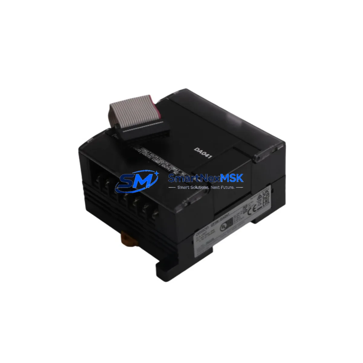
The OMRON CP1W-DA041 is a 4-channel analog output expansion module engineered for seamless integration into CP1W Series programmable logic controller systems. As legacy automation lines face increasing pressure to modernize, the CP1W-DA041 serves as a proven, drop-in retrofit solution for facilities replacing discontinued analog I/O modules, upgrading aging control cabinets, or migrating from earlier OMRON C200H and CQM1 platforms to the current CP1 architecture. With 12-bit resolution across four independently configurable output channels, this module supports both voltage (0–10 V / –10 to +10 V) and current (4–20 mA) signal ranges, making it directly compatible with a wide range of field instruments, variable frequency drives, and proportional control valves already installed in existing production lines.
For engineers managing a retrofit project, the CP1W-DA041 connects directly to the CP1W expansion bus via the right-side expansion connector of any CP1H, CP1L, or CP1E CPU unit. No additional communication card or protocol converter is required. The module occupies one expansion slot and is addressed automatically by the CPU during power-up, eliminating the need for manual DIP switch configuration that was common on older C200H analog output units. This significantly reduces commissioning time and the risk of addressing conflicts when multiple I/O modules share the same rack.
Upgrade Compatibility Table
| Parameter | CP1W-DA041 (This Module) | Legacy Reference (C200H-DA004) |
|---|---|---|
| Output Channels | 4 channels | 4 channels |
| Signal Range | 0–10 V / 4–20 mA (per ch) | 0–10 V / 4–20 mA (per ch) |
| Resolution | 12-bit (1/4000) | 12-bit (1/4000) |
| Bus Interface | CP1W expansion connector | C200H backplane slot |
| CPU Compatibility | CP1H / CP1L / CP1E | C200H / C200HS / CQM1H |
| Address Configuration | Auto (no DIP switch) | Manual DIP switch |
| Program Compatibility | Requires I/O word remapping | Original C200H ladder logic |
| Communication Protocol | CP1W proprietary bus | C200H proprietary bus |
| Mounting | DIN rail, right-side expansion | Backplane card slot |
| Retrofit Recommendation | Direct replacement with address update | Discontinue; migrate to CP1W |
| Commissioning Focus | I/O word mapping, output scaling | Slot address, jumper settings |
| Warranty | 12 Months | N/A (discontinued) |
Retrofit Planning for Existing Automation Systems
A successful retrofit using the CP1W-DA041 begins well before the module arrives on site. The first step is a thorough audit of the existing control cabinet to confirm available expansion slots on the CP1W bus. If the current CPU is a CP1L-M or CP1H-X, up to seven expansion units can be connected in series, which typically provides sufficient capacity to accommodate the CP1W-DA041 alongside existing digital I/O modules such as the CP1W-16ET (16-point transistor output) or the CP1W-40EDT (24 DI / 16 DO combination unit). Engineers should verify the total expansion bus current draw does not exceed the CPU’s rated supply capacity — the CP1W-DA041 draws 80 mA from the 5 V bus, and this must be summed against all other connected expansion units.
Terminal wiring is the next critical checkpoint. The CP1W-DA041 uses a removable screw-terminal block with 0.2–2.5 mm² wire capacity. When replacing a C200H-DA004 installed on a legacy backplane, field wiring connected to the old module’s terminal strip must be carefully re-terminated to the CP1W-DA041’s connector layout. Output channel polarity and signal type (voltage vs. current) must be confirmed against the existing P&ID drawings before energizing the module. If the downstream instruments are 4–20 mA loop-powered transmitters or electropneumatic positioners, the current output mode must be selected via the CPU’s I/O table configuration in CX-Programmer or the newer Sysmac Studio environment.
For sites running OMRON NS-series HMI panels — such as the NS8-TV00B-V2 or NS12-TS01B-V2 — the analog output word addresses referenced in existing HMI screen data bindings must be updated to reflect the new I/O allocation of the CP1W-DA041. Failure to update these address mappings is one of the most common causes of post-retrofit commissioning delays. The HMI project file should be backed up before any address changes are made, and a full screen-by-screen functional test should be completed after the new module is online.
Communication continuity is equally important in multi-node systems. If the CP1 CPU communicates upstream to a SCADA or DCS via OMRON Host Link (FINS/RS-232C) or an EtherNet/IP adapter such as the CP1W-EIP61, the analog output data words must be correctly mapped in the SCADA tag database to avoid process variable mismatches after the retrofit. In systems using a DeviceNet scanner card or a CompoNet master unit, the node address table should be reviewed to confirm no address conflicts arise from the expanded I/O configuration.
Power supply capacity is a frequently overlooked constraint. The existing CP1W-PA205R or CP1W-PD025 power supply unit must be verified to have sufficient headroom to support the additional 80 mA drawn by the CP1W-DA041. If the cabinet already operates near the rated output of the power supply, a higher-capacity unit or a supplementary S8VS-series DIN rail power supply should be considered before the retrofit is finalized.
Downtime Control During System Migration
Minimizing unplanned downtime is the primary operational concern during any analog output module replacement. The recommended approach is to pre-configure the CP1W-DA041 offline using a laptop running CX-Programmer, loading the updated I/O table and verifying the output word assignments before the module is installed in the live cabinet. This offline validation step allows the engineering team to confirm program logic compatibility and catch any word-address conflicts without interrupting production.
On the day of cutover, the sequence should follow a structured lockout/tagout procedure: de-energize the control cabinet, remove the legacy module, install the CP1W-DA041, re-terminate field wiring, restore power, and perform a controlled startup with all analog outputs forced to their safe-state values (typically 4 mA or 0 V) before releasing control to the PLC program. The entire physical swap can typically be completed in under 30 minutes for a single-module replacement, provided the pre-commissioning work has been completed thoroughly.
To protect original program logic, a full backup of the CPU memory — including the ladder program, I/O comments, and data memory (DM) contents — should be saved to a PC and to the CPU’s built-in flash memory (if available on the CP1H or CP1L model in use) before any changes are made. This ensures that if an unexpected issue arises during commissioning, the system can be restored to its pre-retrofit state within minutes. After the CP1W-DA041 is confirmed operational, a final program backup should be saved and archived as the new baseline configuration for the upgraded system.
Retrofit Support FAQ
Q1: Is the CP1W-DA041 a direct drop-in replacement for the C200H-DA004?
A: The CP1W-DA041 provides equivalent 4-channel analog output functionality but uses the CP1W expansion bus rather than the C200H backplane. It is not physically interchangeable. A CPU upgrade to CP1H, CP1L, or CP1E is required, along with I/O word address remapping in the ladder program. We recommend reviewing the OMRON CP1W Expansion Unit Installation Guide before proceeding.
Q2: What wiring changes are needed when installing the CP1W-DA041?
A: Field wiring must be re-terminated to the CP1W-DA041’s removable terminal block. Wire gauge should be 0.2–2.5 mm² (AWG 24–12). Shielded cable is recommended for analog signal runs exceeding 10 meters. Confirm output mode (voltage or current) for each channel via the CPU I/O table before energizing.
Q3: How is the module addressed, and does it conflict with other expansion units?
A: The CP1W-DA041 is addressed automatically by the CPU based on its physical position in the expansion chain. No manual DIP switch setting is required. I/O words are allocated sequentially from the first expansion unit. Use CX-Programmer’s I/O Table function to verify the allocated word range and confirm there are no conflicts with other connected modules such as the CP1W-MAD42 or CP1W-TS002.
Q4: What does the 12-month warranty cover, and how is it validated?
A: All CP1W-DA041 units supplied by SMARTNEXMSK carry a 12-month warranty from the date of shipment. Each unit undergoes pre-shipment functional testing including output signal verification across all four channels at both voltage and current modes. Warranty claims are supported by our technical team at sales@smartnexmsk.com. Proof of purchase and the unit serial number are required to initiate a warranty claim.
© 2026 SMARTNEXMSK. All rights reserved.
Original Source: https://smartnexmsk.com
Contact: sales@smartnexmsk.com | +86 18259474341