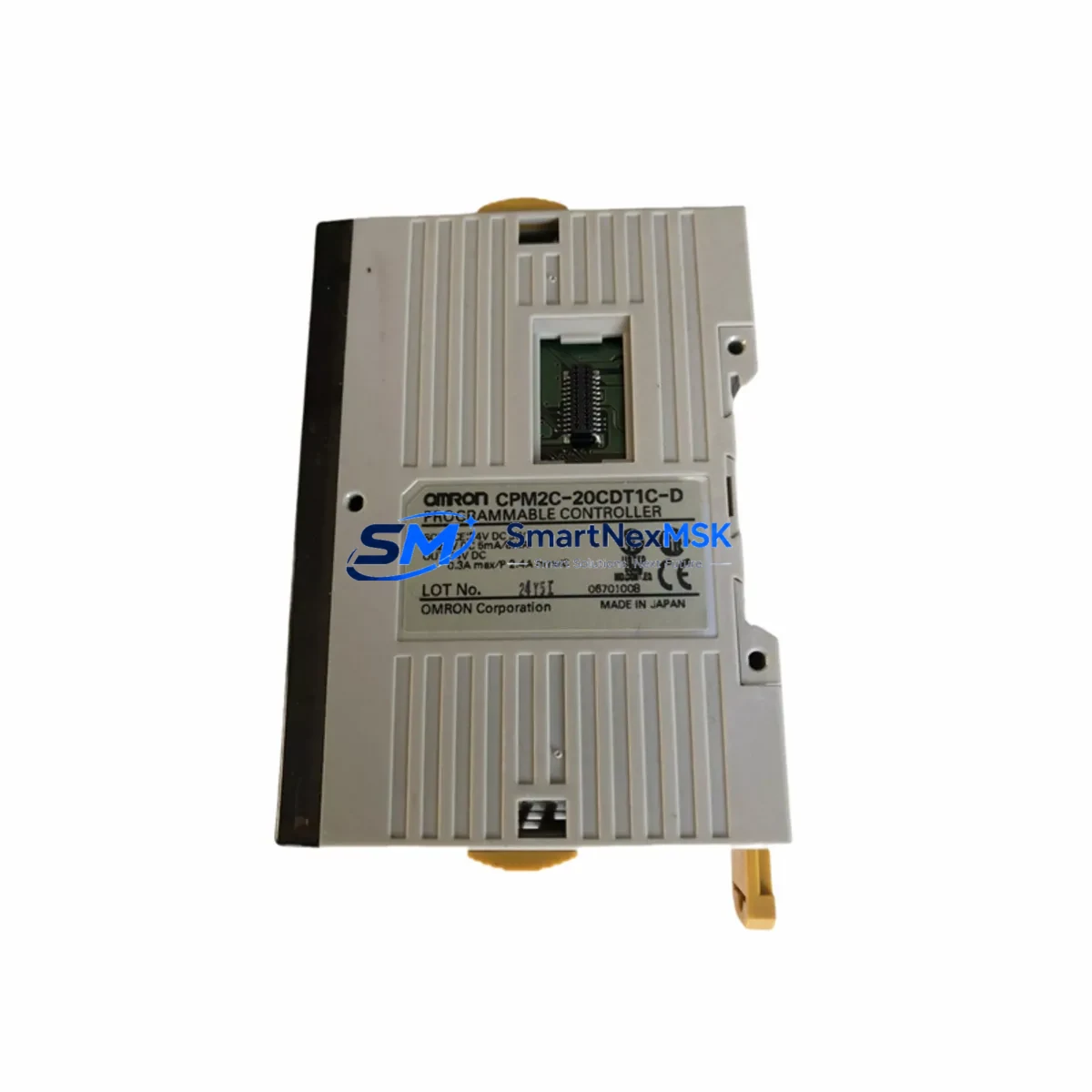
OMRON CPM2C-20CDT1C-D Retrofit-Ready PLC CPU for CPM2C Control Systems
The OMRON CPM2C-20CDT1C-D is a compact, high-reliability PLC CPU module engineered for the Sysmac CPM2C series control platform. Featuring 24 VDC power input, 12 DC inputs, and 8 NPN transistor outputs in a 20-point I/O configuration, this unit is purpose-built for machine-level automation in manufacturing, packaging, and process control environments. As legacy CPM2C installations age and original spare parts become increasingly scarce, the CPM2C-20CDT1C-D remains one of the most sought-after retrofit and replacement components for engineers tasked with extending the operational life of existing control systems without a full platform migration.
Whether you are replacing a failed CPU in a running production line, upgrading a control cabinet to restore redundancy, or migrating from an older CPM1A or CQM1 platform to the CPM2C architecture, this module provides a verified drop-in solution. All units are sourced from authorized supply chains, subjected to pre-shipment functional testing, and covered by a 12-month warranty against manufacturing defects.
Upgrade Compatibility Table
| Parameter | CPM2C-20CDT1C-D Specification | Retrofit / Replacement Notes |
|---|---|---|
| Power Supply | 24 VDC (20.4–26.4 V) | Verify existing cabinet PSU output; compatible with CPM2C-PA201 and CPM2C-PD025 power units |
| I/O Configuration | 12 DC Inputs / 8 NPN Transistor Outputs (20-point) | Confirm terminal wiring map against original I/O assignment; NPN sink output — verify field device polarity |
| Backplane / Rack Interface | CPM2C expansion bus connector | Compatible with CPM2C-32EDT, CPM2C-16ET, and CPM2C-MAD11 expansion modules via side-bus connector |
| Communication | RS-232C peripheral port (built-in) | Supports CX-Programmer via CS1W-CN226 or CS1W-CN626 programming cable; verify baud rate settings in existing program |
| Program Compatibility | Ladder logic, CX-Programmer V9.x+ | Upload existing .CXP project file; verify I/O memory map and DM area assignments before download |
| HMI Interface | Host Link / NT Link (1:1) | Compatible with NS5, NS8, NB series HMI panels; verify screen tag addresses after CPU swap |
| Installation Format | DIN rail or panel mount | Same footprint as CPM2C-10CDT-D and CPM2C-20CDT-D; no bracket modification required |
| Replacement Candidates | CPM2C-20CDT-D, CPM2C-20CDT1-D | Confirm output type (NPN vs PNP) before substitution; CDT1 suffix = NPN transistor output |
| Commissioning | CX-Programmer online monitoring | Perform I/O force test, timer/counter verification, and communication link check before handover |
| Warranty | 12-Month Warranty | Covers manufacturing defects; includes pre-shipment functional test report on request |
Retrofit Planning for Existing Automation Systems
Successful integration of the CPM2C-20CDT1C-D into an aging control system begins well before the module arrives on site. Engineers should start by auditing the existing control cabinet layout, documenting the current terminal block wiring, and confirming the power supply capacity of the installed CPM2C-PA201 or equivalent 24 VDC power unit. The CPM2C series uses a side-bus expansion architecture, meaning any attached CPM2C-32EDT digital expansion modules or CPM2C-MAD11 analog I/O modules will remain fully operational after the CPU swap — provided the expansion bus connector is seated correctly and the I/O table in the replacement program matches the physical module order.
For sites running CPM2C-20CDT1C-D alongside a CPM2C-SRM21-V1 CompoBus/S master module, engineers must verify that the network node addresses and baud rate settings are preserved in the new CPU’s DM area parameters. Similarly, if the control system includes a CPM2C-CIF21 RS-422A/485 adapter for multi-drop serial communication to field instruments or SCADA systems, the communication settings — including station number, baud rate, and data format — must be re-entered or restored from a saved parameter file before the system is returned to service.
HMI integration is another critical checkpoint. Sites using NS5-SQ10B-V2 or NB7W-TW01B touch panels connected via NT Link must verify that all screen tag addresses, alarm setpoints, and recipe data blocks remain consistent with the replacement CPU’s memory map. A mismatch between the HMI screen database and the PLC data area will cause display errors or, in worst cases, incorrect operator commands being sent to field actuators.
For systems that include a CPM2C-CN111 connecting cable linking the CPU to a remote I/O head or a distributed terminal block assembly, the cable pinout and connector orientation should be confirmed against the original wiring diagram. Expansion I/O modules such as the CPM2C-16ET transistor output unit or the CPM2C-8ED digital input module should be powered down before the CPU is removed, and re-energized only after the replacement CPU has been installed and the program downloaded successfully.
All units supplied by SMARTNEXMSK are tested under load conditions prior to shipment. A functional test report is available on request, confirming input response time, output switching performance, and communication port integrity. Stock is maintained for immediate dispatch, with typical lead times of 2–5 business days for standard orders.
Downtime Control During System Migration
Minimizing unplanned downtime during a CPU replacement is the primary concern for maintenance engineers working on live production lines. The recommended approach for CPM2C-20CDT1C-D retrofits is a structured cold-swap procedure: upload the existing ladder program and DM area data from the original CPU using CX-Programmer before any hardware is disturbed, save the project file to a secure location, and print a hard copy of the I/O comment table and cross-reference list for use during commissioning.
Once the replacement CPU is installed and the program downloaded, use CX-Programmer’s online monitoring mode to verify that all input signals are reading correctly before enabling outputs. Force-test critical outputs one at a time — particularly those driving contactors, solenoid valves, or servo drive enable signals — to confirm that the field wiring is intact and the output polarity matches the NPN sink configuration of the CDT1C-D variant. Timer and counter preset values should be verified against the original program documentation, as these are stored in the DM area and may require manual re-entry if the DM backup was not captured prior to the original CPU failure.
For systems where continuous control is required, a parallel commissioning strategy can be employed: install the replacement CPM2C-20CDT1C-D in a test rack alongside a CPM2C-32EDT expansion module, simulate the I/O signals using a portable I/O simulator, and validate the program logic offline before scheduling the live cutover. This approach reduces the live cutover window to under 30 minutes in most cases, protecting production schedules and reducing the risk of commissioning errors under time pressure.
Communication links to upstream SCADA systems or MES platforms should be the last element restored. Confirm that the Host Link station number and baud rate match the SCADA driver configuration before enabling the communication port, and monitor the first 15–30 minutes of operation for any unexpected error flags in the PLC’s error log area.
Retrofit Support FAQ
Q1: Is the CPM2C-20CDT1C-D a direct replacement for the CPM2C-20CDT-D?
The CPM2C-20CDT1C-D and CPM2C-20CDT-D share the same 20-point I/O count and physical form factor, but differ in output type: the CDT1C-D uses NPN (sink) transistor outputs, while the CDT-D uses PNP (source) transistor outputs. Before substituting one for the other, verify the output wiring polarity of all connected field devices. If your existing wiring uses NPN-compatible sensors and actuators, the CDT1C-D is the correct replacement. Program logic and DM area data are fully compatible between the two variants.
Q2: Can I reuse my existing CX-Programmer project file after the CPU swap?
Yes. CX-Programmer project files (.CXP) created for the CPM2C series are fully portable across CPM2C CPU variants. After installing the CPM2C-20CDT1C-D, connect via the built-in RS-232C peripheral port using a CS1W-CN226 programming cable, download the saved project file, and perform an online comparison to verify the downloaded program matches the source file. Ensure the I/O table reflects the physical expansion module configuration before switching the CPU to RUN mode.
Q3: What commissioning checks are required before returning the system to production?
The minimum commissioning checklist for a CPM2C-20CDT1C-D installation includes: (1) verify all input signals in CX-Programmer online monitor, (2) force-test each output channel individually, (3) confirm timer and counter preset values, (4) check DM area parameters for communication settings, (5) verify HMI tag addresses if an NS or NB series panel is connected, and (6) confirm communication link status to any connected CompoBus/S or Host Link devices. Document the results and retain a copy of the final program file as the as-commissioned baseline.
Q4: What does the 12-month warranty cover, and is a test report available?
All CPM2C-20CDT1C-D units supplied by SMARTNEXMSK are covered by a 12-month warranty against manufacturing defects, covering CPU processing failures, I/O channel faults, and communication port malfunctions under normal operating conditions. A pre-shipment functional test report — confirming input response, output switching, and RS-232C port integrity — is available on request at the time of order. Warranty claims are processed within 5 business days of fault confirmation, with replacement units dispatched from stock where available.
© 2026 SMARTNEXMSK. All rights reserved.
Original Source: https://smartnexmsk.com
Contact: sales@smartnexmsk.com | +86 18259474341