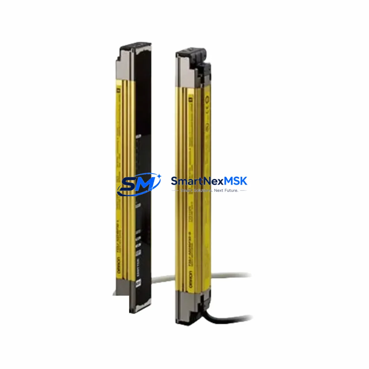
OMRON F3SJ-A0245P14-L Retrofit-Ready Safety Light Curtain for F3SJ-A Series Control Systems
The OMRON F3SJ-A0245P14-L is a Type 4 safety light curtain rated to PLe/SIL3, designed for seamless integration into existing F3SJ-A Series safety architectures. With a 245 mm protective height and 14 mm optical resolution, this unit is engineered to serve as a direct retrofit replacement for aging or discontinued F3SJ-A emitter-receiver pairs on press lines, robotic workcells, packaging machinery, and automated assembly stations. Whether you are upgrading a legacy safety relay circuit or migrating to a modern safety controller platform, the F3SJ-A0245P14-L delivers the electrical and mechanical compatibility required to minimize engineering rework and reduce total downtime during changeover.
Industrial facilities operating older OMRON safety systems frequently encounter obsolescence challenges when original F3SJ-A components reach end-of-life. The F3SJ-A0245P14-L addresses this directly: its M12 quick-disconnect interface and standard DIN-rail-compatible mounting brackets allow technicians to reuse existing conduit runs and cable harnesses without modification. The unit operates on a 24 VDC supply, consistent with the power distribution architecture found in most F3SJ-A Series control cabinets, and its NPN/PNP selectable OSSD outputs maintain backward compatibility with both legacy OMRON G9SA safety relays and current-generation OMRON NX-series safety CPU modules.
Upgrade Compatibility Table
| Parameter | F3SJ-A0245P14-L (This Unit) | Retrofit Notes |
|---|---|---|
| Safety Category | Type 4 / PLe / SIL3 | Maintains existing safety integrity level — no safety re-validation required for like-for-like swap |
| Protective Height | 245 mm | Verify guarding zone dimensions match original installation drawing |
| Optical Resolution | 14 mm | Finger-detection grade; confirm application hazard assessment accepts 14 mm |
| Supply Voltage | 24 VDC ±10% | Compatible with standard F3SJ-A Series 24 VDC panel power supplies |
| Output Type | OSSD × 2 (NPN/PNP selectable) | Direct replacement for existing OSSD wiring to G9SA or NX-series safety relays |
| Connector Interface | M12 5-pin quick-disconnect | Reuse existing M12 cordsets; verify pin-out against original wiring diagram |
| Mounting | Standard F3SJ-A bracket pattern | Existing mounting hardware and alignment fixtures are reusable |
| Communication | Parallel OSSD (standard) | Compatible with F3SJ-A Series muting controllers and bypass modules |
| Commissioning Requirement | Optical axis alignment + OSSD function test | Use F3SJ-A Series alignment indicator LEDs; no special programming tool required |
| Warranty | 12 Months | Covers manufacturing defects; includes pre-shipment functional test certificate |
Retrofit Planning for Existing Automation Systems
A successful retrofit of the F3SJ-A0245P14-L into an operating production line requires systematic pre-work across several engineering disciplines. Begin by auditing the existing control cabinet for available 24 VDC capacity on the safety power rail. The F3SJ-A0245P14-L draws approximately 80 mA per unit (emitter + receiver pair), and if the cabinet also houses an OMRON G9SA-321 safety relay, an NX-SL3300 safety CPU, or an NX-SI3400 safety input unit, the total current budget must be recalculated before energizing the new curtain.
Terminal block wiring is the next critical checkpoint. The F3SJ-A Series uses a standardized five-wire OSSD circuit: +24 V, 0 V, OSSD1, OSSD2, and a test/reset line. If the existing panel uses OMRON XW5T push-in terminal blocks or equivalent spring-clamp terminals, the replacement wiring can be completed without re-ferrulling the entire harness. Technicians should cross-reference the original wiring diagram against the F3SJ-A0245P14-L connection guide to confirm OSSD polarity and muting input assignments before powering up.
For facilities that have already migrated their safety logic to an OMRON NX102 safety controller or an NJ501 machine controller with NX-series safety expansion, the F3SJ-A0245P14-L integrates directly via the existing OSSD input channels without requiring changes to the safety program on the NX-series CPU. However, if the original safety program references specific F3SJ-A diagnostic codes through a serial diagnostic interface, verify whether the replacement unit’s diagnostic output format is identical before closing out the validation checklist.
Backplane and rack considerations apply when the safety system is housed in an OMRON CJ2M CPU rack or a legacy CS1 series rack with a CS1W-SFB21 safety function block unit. In these configurations, the light curtain OSSD signals are typically wired to a dedicated safety I/O module rather than directly to the CPU backplane. Confirm that the safety I/O module — such as an NX-SIH400 high-speed safety input unit — is configured to accept the OSSD pulse-test timing of the F3SJ-A0245P14-L, as mismatched pulse-test windows can cause nuisance trips during initial commissioning.
If the retrofit also involves upgrading the HMI layer, operators using an OMRON NA5 series HMI or an NB7W-TW01B touch panel should update the safety status display screens to reflect the new curtain’s diagnostic LED codes. The F3SJ-A0245P14-L uses a four-state LED indicator (stable green, flashing green, red, and alternating) that maps directly to the standard F3SJ-A Series status word, so existing HMI symbol libraries typically require no modification.
Downtime Control During System Migration
Minimizing production downtime during a safety light curtain retrofit requires a structured changeover plan executed during a scheduled maintenance window. The recommended approach is a parallel-mount verification: install the F3SJ-A0245P14-L alongside the existing curtain on a temporary bracket, complete optical alignment and OSSD function testing while the machine is in a safe-stop state, and only then transfer the OSSD wiring from the old unit to the new one. This sequence ensures that the replacement unit is fully verified before the original is removed, protecting the integrity of the safety function throughout the transition.
Program logic preservation is equally important. If the machine’s safety PLC — whether an OMRON NX-SL3500 or a legacy G9SA-321 relay circuit — has been tuned with specific muting timers, blanking zones, or restart interlock delays, these parameters must be documented before the changeover and re-verified after the new curtain is energized. The F3SJ-A0245P14-L supports fixed blanking and floating blanking configurations that are set via the curtain’s DIP switches, not through the PLC program, so blanking settings from the original unit must be manually transferred to the replacement.
Field continuity is maintained by keeping the safety relay or safety CPU in a monitored-stop state rather than a full power-down wherever the electrical installation permits. This approach preserves the PLC program in RAM, keeps the HMI communication link active, and allows the commissioning technician to perform a live OSSD output test immediately after wiring is complete — reducing total changeover time from several hours to under 60 minutes in most F3SJ-A Series retrofit scenarios. All pre-shipment units from our inventory are function-tested and supplied with a test certificate, further reducing on-site verification time.
Retrofit Support FAQ
Q1: Is the F3SJ-A0245P14-L a direct drop-in replacement for the original F3SJ-A0245P14 (without the -L suffix)?
A: The -L suffix designates the receiver (light receiver) unit of the emitter-receiver pair. It is mechanically and electrically compatible with the standard F3SJ-A Series mounting and wiring scheme. Confirm that your existing installation uses the matching emitter unit (F3SJ-A0245N14 or equivalent) and that the protective height and resolution specifications match your original safety assessment documentation.
Q2: What wiring changes are required when replacing an older F3SJ-A unit with this model?
A: In most cases, no wiring changes are required. The F3SJ-A0245P14-L uses the same M12 5-pin connector pinout as the standard F3SJ-A Series. Reuse existing M12 cordsets and verify OSSD1, OSSD2, +24 V, 0 V, and test-input assignments against the replacement unit’s wiring diagram before energizing. If the original installation used flying-lead cables rather than M12 connectors, a field-wireable M12 adapter is recommended.
Q3: How is compatibility with our existing safety relay or safety PLC verified before installation?
A: Compatibility verification involves three checks: (1) confirm the safety relay or safety CPU accepts OSSD inputs with the F3SJ-A0245P14-L’s pulse-test timing (typically 1 ms OFF-pulse); (2) verify the OSSD output current rating is within the input module’s sink/source capacity; and (3) confirm the safety category and PL/SIL rating of the replacement unit meets or exceeds the original risk assessment requirement. All units are supplied with a pre-shipment functional test certificate to support your incoming inspection process.
Q4: What does the 12-month warranty cover, and is a test certificate included?
A: The 12-month warranty covers manufacturing defects in materials and workmanship from the date of shipment. Each unit undergoes a pre-shipment functional test — including OSSD output verification, optical axis alignment check, and supply voltage tolerance test — and is supplied with a test certificate. Warranty claims are processed through our technical support team at sales@smartnexmsk.com. Damage resulting from incorrect wiring, overvoltage, or mechanical impact is excluded from warranty coverage.
© 2026 SMARTNEXMSK. All rights reserved.
Original Source: https://smartnexmsk.com
Contact: sales@smartnexmsk.com | +86 18259474341