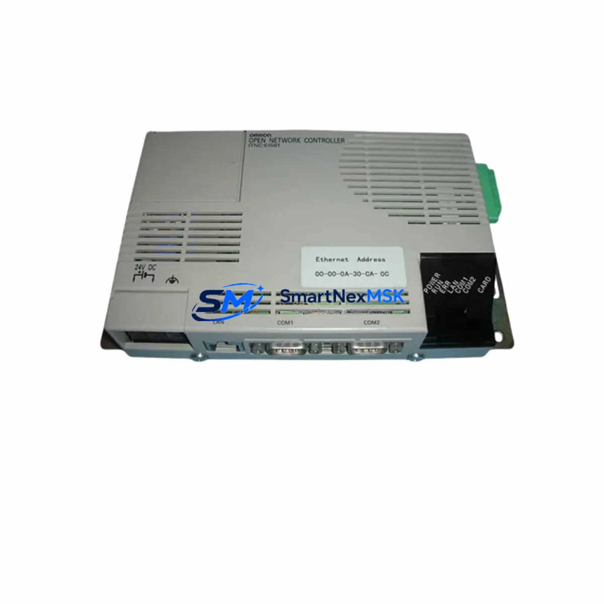
OMRON ITNC-EIS01-DRM Retrofit-Ready Ethernet/DeviceNet Gateway for ITNC Series Control Systems
The OMRON ITNC-EIS01-DRM is an Ethernet-to-DeviceNet gateway module designed for the ITNC Series Open Network Controller platform. As legacy ITNC-based control systems approach end-of-life or require communication infrastructure upgrades, the ITNC-EIS01-DRM serves as a critical bridge component — enabling engineers to modernize network topology without replacing the entire control architecture. Whether you are migrating from a proprietary fieldbus to a more open DeviceNet backbone, expanding I/O capacity across distributed nodes, or restoring a failed gateway in a production-critical environment, this module provides a verified, drop-in compatible solution backed by a 12-month warranty and pre-shipment functional testing.
In retrofit scenarios, the ITNC-EIS01-DRM is typically installed alongside the ITNC-EIS01 controller unit, sharing the same backplane slot configuration and power rail. Engineers replacing a failed or obsolete gateway should first verify the existing backplane’s slot addressing and confirm that the ITNC Series rack — often a CS1W-BC023 or CS1W-BC083 style chassis — has sufficient available slots and power budget. The module draws power from the rack’s internal 5 VDC bus, so total rack power consumption must be recalculated when adding or replacing modules, particularly when the rack also hosts CS1W-ID211 digital input modules, CS1W-OD211 digital output modules, or CS1W-AD041 analog input modules in adjacent slots.
Upgrade Compatibility Table
| Parameter | ITNC-EIS01-DRM | Notes / Retrofit Guidance |
|---|---|---|
| Communication Interface | Ethernet (10/100BASE-TX) + DeviceNet | Verify existing Ethernet switch supports auto-negotiation; DeviceNet trunk cable must be terminated at both ends |
| Mounting / Installation | ITNC Series backplane slot | Confirm slot number matches original module address; re-address if slot position changes |
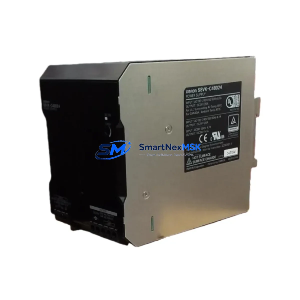
| Power Requirement | 5 VDC via backplane (internal) | Recalculate total rack power budget; add PA205 or PA206 power supply if margin is insufficient |
| DeviceNet Compatibility | Master / Slave configurable | Node address and baud rate (125K / 250K / 500K) must match existing network configuration |
| Program Compatibility | Compatible with CX-Programmer ladder logic referencing original I/O map | Verify I/O memory area assignments; no re-compilation required if slot address is unchanged |
| HMI Integration | Ethernet-based; compatible with NS-series HMI via Ethernet/IP or FINS/TCP | Update HMI screen PLC node address if IP address changes during retrofit |
| Replacement Recommendation | Direct replacement for failed or EOL ITNC-EIS01-DRM units | No firmware update required for same-series replacement; confirm firmware version for cross-series migration |
| Warranty | 12-Month Warranty | Includes pre-shipment functional test; defective units replaced or refunded within warranty period |
Retrofit Planning for Existing Automation Systems
A successful retrofit begins well before the module arrives on-site. Start by documenting the existing ITNC Series network topology: identify all DeviceNet slave nodes — including remote I/O terminals such as DRT2-ID16 or DRT2-OD16 distributed I/O blocks — and record their node addresses, baud rates, and wiring configurations. The DeviceNet trunk cable polarity (V+, CAN_H, Shield, CAN_L, V−) must be verified at the drop line connection point to the ITNC-EIS01-DRM’s DeviceNet port.
On the Ethernet side, confirm the module’s IP address, subnet mask, and default gateway settings using CX-Integrator or the ITNC Series configuration tool. If the replacement module is assigned a different IP address than the original, all upstream SCADA systems, NS-series HMI panels, and FINS/TCP communication nodes must be updated accordingly. Failure to update HMI screen PLC node references is one of the most common causes of post-retrofit communication faults.
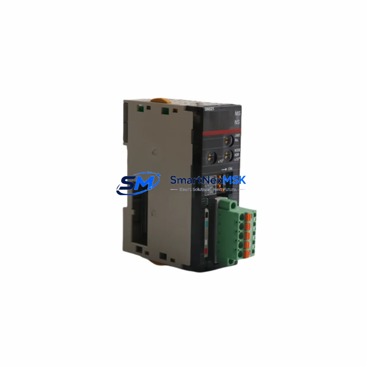
For systems that also include a CJ1W-DRM21 DeviceNet master unit or a CS1W-DRM21 in a parallel rack, ensure that the master’s scan list is updated to reflect any node address changes introduced during the retrofit. If the control system uses a CJ2M-CPU31 or CJ2M-CPU33 as the host controller, verify that the FINS routing table entries referencing the ITNC-EIS01-DRM’s network address remain consistent after module replacement.
Power supply integrity is equally critical. If the existing PA205 or PA206 rack power supply is operating near its rated output, adding a replacement module with slightly different inrush characteristics can trigger nuisance tripping. Measure actual rack current draw before and after module installation. In high-density racks that also host CJ1W-SCU41-V1 serial communication units or CJ1W-EIP21 EtherNet/IP units, power margin calculations must account for all installed modules simultaneously.
Terminal wiring on the DeviceNet connector should be inspected and re-terminated if the existing ferrules show signs of oxidation or mechanical fatigue. Use shielded DeviceNet-compliant cable (thick or thin trunk) and ensure the shield drain wire is grounded at one end only to prevent ground loop interference. Label all terminal connections before disconnecting the original module to facilitate accurate re-wiring of the replacement ITNC-EIS01-DRM.
Downtime Control During System Migration
Minimizing production downtime during a gateway module replacement requires a structured pre-outage preparation protocol. Before taking the system offline, export the full CX-Programmer project file and create a verified backup of the ITNC controller’s memory — including DM area data, I/O memory, and task program files. Store backups on an isolated engineering laptop, not on the production network, to prevent accidental overwrite.
If the control system supports online editing, use CX-Programmer’s online monitoring mode to capture the current state of all DeviceNet node statuses and I/O data link tables immediately before shutdown. This snapshot serves as the baseline for post-retrofit verification. For systems where the ITNC-EIS01-DRM handles time-critical I/O data exchange, coordinate the maintenance window with production scheduling to align with natural process breaks — shift changes, batch completion points, or scheduled cleaning cycles.
During the physical swap, power down the rack using the correct sequence: disable the DeviceNet network master first, then remove power from the rack via the PA205 or PA206 power supply. Insert the replacement ITNC-EIS01-DRM into the correct backplane slot, re-connect all terminal wiring per the pre-documented layout, and restore power. The module’s LED indicators (MS, NS, and DeviceNet status LEDs) provide immediate diagnostic feedback: a solid green MS LED confirms normal operation, while a flashing red NS LED indicates a network configuration mismatch that must be resolved before returning the system to automatic mode.
Post-installation, use CX-Integrator to verify that all DeviceNet slave nodes have re-established communication and that the I/O data link tables are active. Confirm HMI screen data refresh rates are normal and that any SCADA historian tags linked to the ITNC network are receiving valid data. A structured commissioning checklist — covering power-up sequence, LED status verification, DeviceNet node scan, FINS communication test, HMI screen validation, and a 15-minute monitored run — ensures the retrofit is complete before handing control back to the operations team.
Retrofit Support FAQ
Q1: Is the ITNC-EIS01-DRM a direct drop-in replacement for a failed unit in the same rack slot?
Yes. If the replacement module is installed in the same backplane slot as the original, no changes to the CX-Programmer I/O map or DeviceNet scan list are required. The module inherits the slot address automatically. Confirm the DeviceNet node address DIP switch settings match the original configuration before powering up.
Q2: What wiring checks are required before installing the replacement module?
Inspect the DeviceNet connector for pin oxidation, loose ferrules, and correct polarity (V+, CAN_H, Shield, CAN_L, V−). Verify trunk cable termination resistors (121 Ω) are present at both ends of the DeviceNet segment. On the Ethernet side, confirm the RJ-45 connector and patch cable are undamaged and that the connected switch port is set to auto-negotiate.
Q3: Will the existing ladder logic program need to be modified after replacing the ITNC-EIS01-DRM?
In most same-slot replacements, no program modification is needed. The I/O memory area assignments and DeviceNet data link tables remain valid as long as the slot address and node address are unchanged. If the retrofit involves moving the module to a different slot or changing the DeviceNet node address, update the CX-Programmer I/O table and re-download the modified project to the controller.
Q4: What does the 12-month warranty cover, and what pre-shipment testing is performed?
Every ITNC-EIS01-DRM unit undergoes functional testing prior to shipment, including power-up verification, Ethernet port link establishment, and DeviceNet communication initialization. The 12-month warranty covers manufacturing defects and functional failures under normal operating conditions. Units that fail within the warranty period are replaced or refunded. Damage caused by incorrect wiring, overvoltage, or physical mishandling is excluded from warranty coverage.
© 2026 SMARTNEXMSK. All rights reserved.
Original Source: https://smartnexmsk.com
Contact: sales@smartnexmsk.com | +86 18259474341