OMRON OPIC1 Maintenance-Ready Spare for E3X Automation
The OMRON OPIC1 is an original fiber optic amplifier controller designed for the E3X series sensing system, widely deployed across discrete manufacturing, automotive assembly, food processing, and semiconductor fabrication lines. When an OPIC1 unit fails or degrades in the field, the downstream impact is immediate: conveyor detection halts, reject logic fails, and production throughput drops. Sourcing a verified original replacement with confirmed E3X compatibility is the fastest path to restoring normal operation without re-engineering the sensing circuit.
This listing supplies the OMRON OPIC1 as a maintenance-ready spare — inspected, function-tested prior to dispatch, and backed by a 12-month warranty. Each unit ships with full electrical verification to confirm output switching response, power consumption within rated spec, and fiber channel sensitivity alignment. For maintenance engineers managing aging E3X installations or building a proactive spare parts inventory, the OPIC1 is a direct drop-in replacement that requires no firmware changes, no re-wiring of the fiber head connector, and no recalibration of the amplifier threshold when replacing a like-for-like unit.
Procurement engineers sourcing for MRO stock or emergency breakdown kits will find this unit available for immediate dispatch. Long-term supply continuity is supported for customers requiring scheduled replenishment across multiple plant locations.
Spare Maintenance Table
| Parameter | Specification |
|---|---|
| Part Number / SKU | OPIC1 |
| Brand | OMRON |
| Series | E3X Fiber Optic Amplifier Series |
| Product Type | Fiber Optic Amplifier Controller |
| Supply Voltage | 12–24 V DC (±10%) |
| Output Type | NPN / PNP open-collector (series-dependent) |
| Response Time | ≤ 1 ms (standard mode) |
| Operating Temperature | –10°C to +55°C |
| Protection Rating | IP40 (controller body) |
| Fiber Head Compatibility | E3X series fiber units (E32 family) |
| Mounting | DIN rail or panel mount via E39 bracket |
| Country of Origin | Japan |
| Warranty | 12 Months from dispatch date |
| Pre-shipment Test | Output switching, sensitivity, power draw verified |
| Replacement Compatibility | Direct drop-in for existing E3X amplifier slots |
| Application Environments | Automotive, food & beverage, semiconductor, general manufacturing |
| Maintenance Recommendation | Inspect fiber connectors and cable routing at each replacement; clean fiber end faces before re-insertion |
Maintenance Planning for Continuous Operation
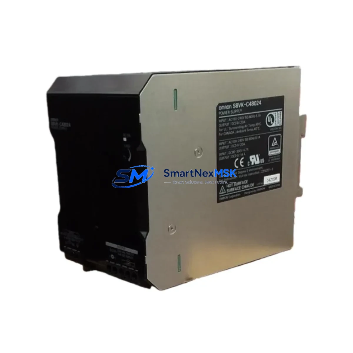
Replacing an OPIC1 amplifier controller is rarely an isolated task. A disciplined maintenance engineer will treat the replacement as an opportunity to audit the entire sensing circuit and adjacent control components. Begin by verifying the 24 V DC supply rail feeding the amplifier — a degraded power supply module (such as an OMRON S8VS or equivalent DIN-rail PSU) can cause intermittent amplifier resets that mimic fiber head faults. Check the terminal block connections at the amplifier input and output; loose or corroded terminals on Phoenix Contact or Weidmüller-style terminal strips are a common source of signal instability in high-vibration environments.
Inspect the E32-series fiber optic cables routed to the OPIC1. Bent, kinked, or contaminated fiber ends reduce light intensity and cause false detection. If the fiber cable shows physical damage, replace it alongside the OPIC1 rather than risk a repeat fault within weeks. For installations where the OPIC1 feeds a signal into a PLC input card — such as an OMRON CJ1W-ID211 or CJ2M CPU-series digital input module — verify that the input card’s threshold voltage is within spec and that the wiring from the amplifier output to the PLC terminal is intact and correctly shielded.
In control cabinets where the E3X system is integrated with relay output modules (for example, OMRON G2R or MY series relays used to drive actuators based on sensor output), inspect the relay coil voltage and contact condition. A relay with worn contacts can introduce latency or missed switching events that are incorrectly attributed to the amplifier. Similarly, if the OPIC1 output connects through a signal isolator or barrier — common in hazardous-area or long-cable installations — verify the isolator’s input/output voltage drop and response time remain within the amplifier’s rated load spec.
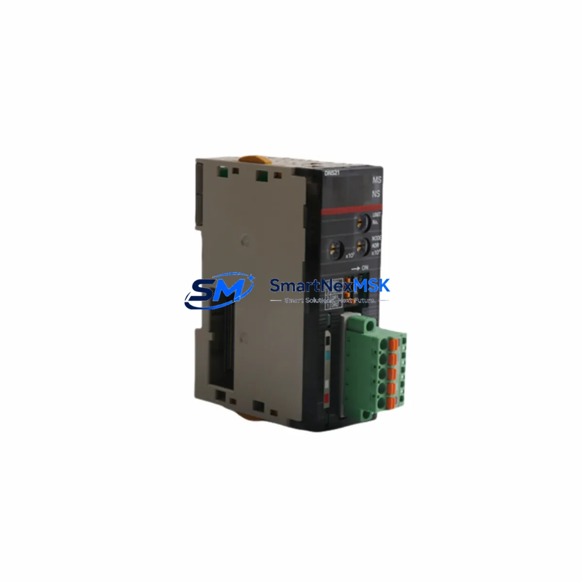
For systems using an OMRON NS-series or NB-series HMI to display sensor status, confirm that the HMI tag mapping to the OPIC1 output bit is still valid after replacement, particularly if the PLC program uses absolute I/O addresses. Communication modules such as the OMRON CJ1W-SCU21 or EtherNet/IP adapter cards should also be checked for firmware compatibility if the control system has undergone any software updates since the original OPIC1 was installed. Finally, review the fuse or circuit breaker protecting the 24 V sensor supply branch — a slow-blow fuse rated at 1–2 A is standard practice for protecting amplifier circuits, and a degraded fuse can cause nuisance trips under normal load.
Site Replacement Workflow
To replace a failed OPIC1 with minimum downtime, follow this field-proven sequence. First, isolate the 24 V DC supply to the amplifier circuit and confirm de-energization with a multimeter before disconnecting any wiring. Label all terminal connections on the existing unit before removal — a photograph of the wiring is a reliable backup. Remove the OPIC1 from its DIN rail slot or panel mount, disconnect the fiber head, and note the sensitivity and mode settings displayed on the unit (if still readable) so they can be replicated on the replacement.
Install the new OPIC1, reconnect the fiber head, and restore the 24 V supply. Set the amplifier sensitivity to match the previous configuration using the teach function or manual threshold adjustment. Verify output switching by triggering the fiber head with the target object and confirming the PLC input bit changes state correctly. Run a short functional test cycle before returning the machine to production. Document the replacement date, unit serial number, and post-installation test results in the maintenance log — this data supports warranty claims and informs future spare parts planning.
For older E3X installations where the original OPIC1 model has been superseded, the replacement unit is electrically and mechanically compatible with the existing fiber head and wiring, eliminating the need for panel modifications or PLC program changes. This compatibility assurance reduces the engineering time required for each replacement and supports the goal of extending the operational life of legacy automation systems without costly full-system upgrades.
Spare Parts Support FAQ
Q1: Is this OPIC1 unit an original OMRON product or an aftermarket substitute?
This is an original OMRON OPIC1 unit sourced through established industrial supply channels. Each unit undergoes pre-shipment electrical testing to verify output switching performance, power consumption, and fiber sensitivity response before dispatch. A 12-month warranty is provided from the date of shipment.
Q2: How do I confirm compatibility with my existing E3X installation before ordering?
The OPIC1 is designed for the OMRON E3X fiber optic amplifier series and is compatible with E32-family fiber heads and standard 12–24 V DC industrial sensor wiring. If your installation uses a specific E3X sub-variant or a non-standard fiber connector, please contact us with your existing unit’s label information and we will confirm compatibility before processing your order.
Q3: What is the recommended spare parts stocking strategy for OPIC1 units?
For production lines with multiple E3X sensing points, we recommend maintaining a minimum of one OPIC1 spare per 10 installed units, with a higher ratio for critical detection stations where a fault would halt the entire line. For plants operating 24/7 shifts, holding two units on-site eliminates the risk of extended downtime during off-hours breakdowns when same-day procurement is not possible.
Q4: What does the 12-month warranty cover, and how is a warranty claim processed?
The 12-month warranty covers electrical failure under normal operating conditions, including output switching failure, power circuit faults, and sensitivity drift beyond rated specification. Physical damage caused by incorrect installation, overvoltage, or environmental exposure outside the rated operating range is excluded. To initiate a warranty claim, contact us with the order reference, installation date, and a description of the fault. Replacement units are dispatched after fault verification, with return shipping coordinated on a case-by-case basis.
© 2026 SMARTNEXMSK. All rights reserved.
Original Source: https://smartnexmsk.com
Contact: sales@smartnexmsk.com | +86 18259474341