OMRON SRT2-ID16T-1 Maintenance-Ready Spare for CompoBus/S Automation
The OMRON SRT2-ID16T-1 is a 16-point NPN transistor input slave module designed for CompoBus/S (SRT2 Series) distributed I/O networks. In industrial automation environments — from automotive assembly lines to food processing facilities — this module serves as a critical field-level input node, collecting digital signals from proximity sensors, limit switches, and push-button stations and transmitting them to the host PLC over the CompoBus/S serial bus. When this module fails or degrades, the entire I/O segment it serves goes offline, triggering unplanned downtime that can cost thousands per hour. Maintaining a verified original spare on the shelf is the single most effective strategy for rapid downtime recovery.
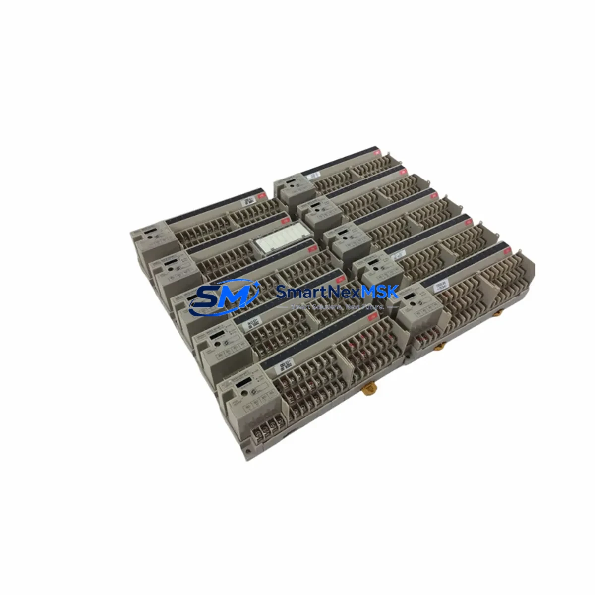
This listing provides a tested, original OMRON SRT2-ID16T-1 spare unit, sourced from authorized supply channels, inspected before shipment, and backed by a 12-month warranty. Each unit is verified for CompoBus/S bus compatibility, NPN input logic, and correct terminal block configuration before dispatch.
Spare Maintenance Table
| Parameter | Specification |
|---|---|
| Model / SKU | SRT2-ID16T-1 |
| Brand | OMRON |
| Series | SRT2 (CompoBus/S) |
| Module Type | Remote I/O Input Slave Module |
| Input Points | 16 Points, NPN Transistor |
| Communication Bus | CompoBus/S (High-speed / Long-distance mode) |
| Input Voltage | 24 VDC (12–24 VDC range) |
| Current Consumption | ≤ 80 mA (at 24 VDC) |
| Connector Type | Terminal block (T-1 suffix = screw terminal) |
| Compatibility | OMRON SRM1, C200HX/HG/HE, CQM1H, CS1 with CompoBus/S master units |
| Operating Temperature | 0 to 55°C |
| Protection Rating | IP20 (panel-mount) |
| Country of Origin | Japan |
| Installation | DIN rail or direct panel mount |
| Maintenance Recommendation | Inspect terminal tightness, bus cable continuity, and node address DIP switches at each planned maintenance interval |
| Warranty | 12 Months from date of shipment |
Maintenance Planning for Continuous Operation
When a maintenance or procurement engineer schedules replacement of the SRT2-ID16T-1, the replacement event should be treated as a broader control-cabinet health check rather than a single-component swap. The SRT2-ID16T-1 operates within a CompoBus/S segment that depends on the integrity of multiple upstream and downstream components.
Begin by verifying the CompoBus/S master unit — typically an SRM1-C02 or a C200HW-SRM21-V1 — for bus error flags and node registration status. A degraded master can cause repeated slave faults that are misdiagnosed as module failures. Next, inspect the 24 VDC power supply module feeding the I/O segment; voltage sag below 21.6 VDC will cause NPN input thresholds to drift, producing intermittent false signals. Units such as the S8VS-06024 or equivalent DIN-rail PSU should be load-tested during the maintenance window.
Check the CompoBus/S flat cable or round cable trunk and all T-branch connectors for insulation damage, connector oxidation, or improper termination resistors. A missing or incorrect termination resistor (typically 120 Ω) at the bus ends is a common root cause of communication errors that appear as module faults. While the cable is accessible, verify the node address DIP switch settings on the SRT2-ID16T-1 replacement unit match the original configuration — a mismatch will prevent the slave from registering on the bus.
Inspect adjacent SRT2-series output modules such as the SRT2-OD16T or SRT2-ROC08 relay output slave in the same cabinet. These modules share the same bus segment and power rail; a shorted output channel on a neighboring module can cause bus-wide communication disruption. Similarly, review the terminal blocks and wiring ferrules on the input side — loose or corroded terminals on 0.5 mm² sensor cables are a leading cause of intermittent input faults in high-vibration environments.
For systems using OMRON CS1 or CJ1 PLCs with CompoBus/S interface cards, confirm the I/O table allocation in the PLC program still matches the node count after replacement. If the maintenance event involves upgrading from an older SRT2-ID16 (without the T-1 terminal suffix) to the SRT2-ID16T-1, verify that the wiring gauge is compatible with the screw terminal pitch. Finally, check any signal isolators or surge protection modules installed on long sensor cable runs — devices such as the OMRON G3PA or equivalent DIN-rail isolators should be inspected for thermal discoloration or relay contact wear during the same maintenance window.
Site Replacement Workflow
Replacing the SRT2-ID16T-1 on a live production site requires a structured approach to minimize downtime and avoid configuration errors. Before removing the faulty module, photograph or document the existing DIP switch node address settings and all terminal wiring positions. Power down the 24 VDC supply to the I/O segment — do not rely solely on the PLC program to suppress outputs during the swap.
Remove the terminal block wiring systematically, labeling each wire if pre-labeled ferrules are not already in place. Disconnect the CompoBus/S bus connector and remove the module from the DIN rail. Install the replacement SRT2-ID16T-1, set the node address DIP switches to match the documented configuration, reconnect the bus cable, and re-terminate the input wiring. Restore 24 VDC power and observe the module’s LED indicators: the PWR LED should illuminate green, and the COMM LED should flash or illuminate to indicate active bus communication. If the COMM LED remains off or flashes an error pattern, verify bus termination, node address, and master unit registration.
After confirming bus communication, perform a functional input test by actuating each connected sensor and verifying the corresponding input bit in the PLC I/O monitor. This step confirms both the module replacement and the wiring integrity. Total replacement time for a prepared technician with a spare unit on hand is typically 15–30 minutes, compared to 4–24 hours waiting for emergency procurement. This is the core value of maintaining a stocked SRT2-ID16T-1 spare in your control-room inventory.
Spare Parts Support FAQ
Q1: Is this SRT2-ID16T-1 compatible with both high-speed and long-distance CompoBus/S modes?
Yes. The SRT2-ID16T-1 supports both CompoBus/S operating modes. The mode is selected at the master unit level (SRM1 or C200HW-SRM21-V1), not at the slave module. Ensure the master’s mode setting matches your existing network configuration before commissioning the replacement unit.
Q2: What is the difference between SRT2-ID16 and SRT2-ID16T-1?
The base SRT2-ID16 uses a connector-type (MIL connector) input interface, while the SRT2-ID16T-1 uses a screw terminal block (T-1 suffix). Both provide 16-point NPN digital inputs on CompoBus/S. When replacing an SRT2-ID16 with an SRT2-ID16T-1, rewiring to the screw terminal format is required. Electrically and functionally, the modules are equivalent on the bus.
Q3: How is each unit tested before shipment?
Every SRT2-ID16T-1 unit undergoes a pre-shipment inspection covering power-on self-test, LED indicator verification, terminal block integrity check, and visual inspection for physical damage. Units that do not pass inspection are not shipped. The 12-month warranty covers manufacturing defects and functional failures under normal operating conditions.
Q4: Can you support long-term or recurring spare parts orders for this model?
Yes. We maintain ongoing stock of SRT2-series CompoBus/S modules to support planned maintenance programs, annual spare parts budgets, and emergency replacement needs. Contact our team to discuss blanket order arrangements, lead time commitments, and multi-unit pricing for your maintenance inventory plan.
© 2026 SMARTNEXMSK. All rights reserved.
Original Source: https://smartnexmsk.com
Contact: sales@smartnexmsk.com | +86 18259474341