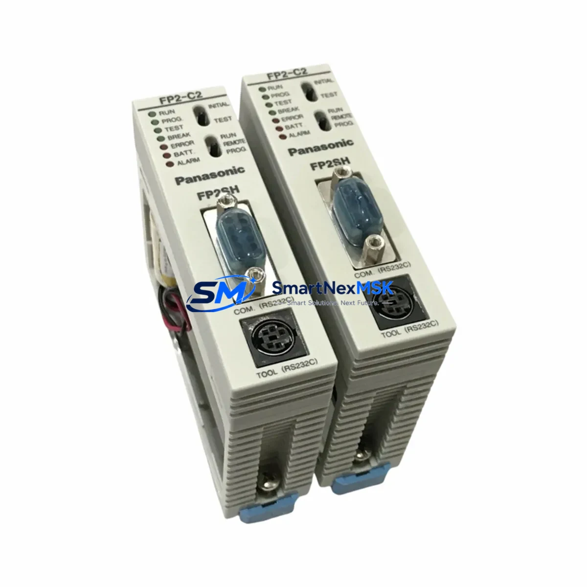
Panasonic FP2-C2T32 Retrofit-Ready CPU for FP2 Control Systems: Seamless Compatibility & Legacy System Upgrade
The Panasonic FP2-C2T32 is a high-performance CPU module engineered for the FP2 Series programmable logic controller platform. As production lines age and original FP2 CPU units reach end-of-life, the FP2-C2T32 serves as the definitive retrofit-ready replacement — enabling engineers to restore full control system functionality without redesigning the control cabinet, rewriting ladder logic from scratch, or replacing the entire rack infrastructure.
Whether you are recovering from an unplanned CPU failure, executing a planned modernization of a legacy automation cell, or sourcing a long-term spare for a critical production line, the FP2-C2T32 delivers the compatibility, reliability, and documentation support that industrial maintenance teams demand.
Upgrade Compatibility Table
| Parameter | FP2-C2T32 Specification | Retrofit Notes |
|---|---|---|
| Backplane Interface | FP2 Series backplane bus | Direct fit into FP2-BP08 / FP2-BP16 racks; no adapter required |
| Communication Protocol | MEWTOCOL-COM / MEWTOCOL-DAT | Compatible with existing SCADA, HMI, and upper-level PC links |
| Programming Interface | Toolport (mini-DIN) + Ethernet option | Use existing FP-Programmer II cable or USB-miniDIN adapter |
| I/O Capacity | Up to 1,024 I/O points (with expansion) | Existing FP2-X32T / FP2-X16T I/O modules remain fully compatible |
| Power Requirement | 5 VDC via backplane (from FP2-PSA2 / FP2-PSA3 power supply) | Verify PSU current budget before installation; no external wiring change |
| Program Memory | 32K steps | Existing programs within capacity upload directly via FPWIN Pro 7 |
| Installation Format | Slot 0 of FP2 rack | Slide-in replacement; DIN rail and panel mount unchanged |
| Replacement Compatibility | FP2-C1 / FP2-C2 / FP2-C2T series | Confirm program step count and I/O address map before swap |
| Commissioning Tool | FPWIN Pro 7 (Windows 10/11) | Legacy FPWIN Pro 5 projects importable with minor conversion |
| Warranty | 12-Month Warranty | Covered from date of shipment; includes functional test certificate |
Retrofit Planning for Existing Automation Systems
A successful FP2-C2T32 retrofit begins well before the module arrives on site. The first step is a thorough audit of the existing control cabinet. Engineers should document the current FP2-PSA2 or FP2-PSA3 power supply output capacity and confirm that the 5 VDC bus current budget accommodates the replacement CPU alongside all installed I/O modules — including any FP2-X32T digital input modules, FP2-Y32T transistor output modules, and FP2-A4 analog I/O modules already occupying the rack slots.
Terminal wiring on the I/O modules does not change during a CPU swap, which significantly reduces retrofit risk. However, engineers must verify that the FP2-BP08 or FP2-BP16 backplane bus connectors are clean and free of corrosion before seating the new CPU. A damaged backplane connector is one of the most common causes of post-retrofit communication faults and should be inspected as part of the pre-installation checklist.
For systems that include a FP2-ET1 Ethernet communication module or an FP2-CCL CC-Link interface module, the module address settings and station number DIP switches must be recorded before the CPU is removed. These settings are independent of the CPU but are frequently disturbed during rack servicing. Restoring them incorrectly will cause network communication failures that can be misdiagnosed as CPU faults.
HMI panels connected via RS232C or RS485 — such as Panasonic GT series terminals or third-party SCADA systems using MEWTOCOL-COM — should be placed in offline or maintenance mode before the CPU swap begins. After the FP2-C2T32 is installed and powered, re-establish the HMI communication link and verify that all screen data points are reading correctly before releasing the line. If the HMI project references specific CPU memory addresses (DT, WX, WY registers), confirm that the address map in the replacement CPU program matches the original.
Program upload from the original CPU — if it is still partially functional — should be performed using FPWIN Pro 7 connected via the Toolport mini-DIN interface or a USB-to-Toolport adapter cable. Save the verified program backup to at least two separate storage locations before proceeding with the physical swap. For sites where the original CPU has already failed completely, SMARTNEXMSK maintains a library of common FP2 Series program templates and can assist with program reconstruction based on I/O lists and functional descriptions.
Downtime Control During System Migration
Minimizing production downtime during a CPU replacement requires a structured, time-boxed approach. The recommended sequence for an FP2-C2T32 swap is: (1) place the line in a safe, controlled stop state using the existing E-stop or safety relay circuit; (2) switch the CPU RUN/PROG switch to PROG mode and confirm all outputs are de-energized; (3) upload and verify the existing program via FPWIN Pro 7; (4) power down the rack via the FP2-PSA2 main breaker; (5) remove the failed CPU from Slot 0 and seat the FP2-C2T32; (6) restore power and confirm the CPU enters PROG mode without error LEDs; (7) download the verified program; (8) perform a controlled RUN mode test with outputs inhibited; (9) release outputs and return the line to production.
This sequence, when pre-planned and rehearsed with the maintenance team, can typically be completed within 60 to 90 minutes for a standard FP2 rack configuration. Pre-staging the replacement FP2-C2T32, the programming cable, a laptop with FPWIN Pro 7 installed, and a printed copy of the I/O address map at the control cabinet before the planned maintenance window eliminates the most common sources of delay.
For critical 24/7 production environments, SMARTNEXMSK recommends maintaining at least one FP2-C2T32 as a cold-standby spare. Given the discontinued status of many FP2 Series components, on-shelf availability cannot be guaranteed from OEM channels, and lead times for new production runs can exceed 16 weeks. Stocking a verified spare eliminates this risk entirely and reduces mean time to repair (MTTR) to under two hours for any CPU-related fault.
Retrofit Support FAQ
Q1: Is the FP2-C2T32 a direct drop-in replacement for the FP2-C2 and FP2-C1 CPU modules?
A: In most cases, yes. The FP2-C2T32 uses the same backplane connector and occupies Slot 0 of any FP2 Series rack, including the FP2-BP08 and FP2-BP16. The primary compatibility check is program step count — if the existing program exceeds 32K steps, a higher-capacity CPU variant is required. I/O module wiring and terminal assignments are unaffected by the CPU swap.
Q2: Can I reuse my existing FPWIN Pro 5 program files with the FP2-C2T32?
A: Yes, with a conversion step. FPWIN Pro 7 includes a project import utility that converts FPWIN Pro 5 (.FPW) files to the current format. After conversion, review all special relay and data register references, as some system memory addresses were remapped between software versions. A test download to the FP2-C2T32 in PROG mode with outputs inhibited is strongly recommended before returning the system to production.
Q3: What pre-shipment testing does SMARTNEXMSK perform on the FP2-C2T32?
A: Every FP2-C2T32 unit undergoes a functional power-on test, communication port verification via MEWTOCOL protocol, and a program download/upload cycle before shipment. A test certificate is included with each unit. The 12-month warranty covers all functional defects from the date of shipment and includes technical support for installation and commissioning questions.
Q4: How do I verify that the FP2-C2T32 is communicating correctly with my HMI and SCADA system after installation?
A: After installing the FP2-C2T32 and downloading the program, place the CPU in RUN mode and use FPWIN Pro 7’s online monitoring function to confirm that I/O status matches field conditions. Then check the HMI communication link — for MEWTOCOL-COM over RS232C, verify baud rate, station number, and parity settings match the HMI project configuration. For Ethernet-connected SCADA systems using the FP2-ET1 module, ping the module IP address and confirm data register polling is active before releasing the line to production.
© 2026 SMARTNEXMSK. All rights reserved.
Original Source: https://smartnexmsk.com
Contact: sales@smartnexmsk.com | +86 18259474341