Panasonic FP2-DA4 Maintenance-Ready Spare for FP2 Series Automation
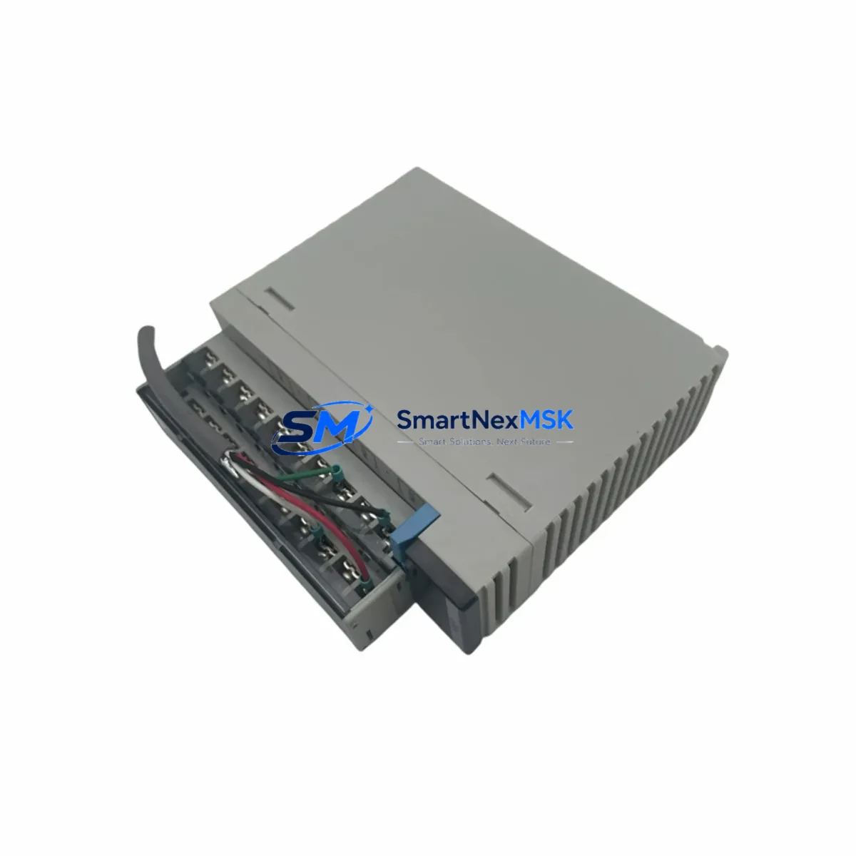
The Panasonic FP2-DA4 is a 4-channel analog output module designed for the FP2 Series programmable logic controller platform. As a critical signal-conditioning component in process control and factory automation systems, the FP2-DA4 converts digital values from the CPU into precise analog voltage or current signals that drive field devices such as variable-frequency drives, proportional valves, servo amplifiers, and process transmitters. When this module fails or degrades, the entire analog control loop is disrupted — leading to uncontrolled actuator behavior, process deviation alarms, and unplanned downtime that can cascade across production lines.
At SMARTNEXMSK, every FP2-DA4 unit is sourced as an original Panasonic spare, individually tested for output accuracy and channel isolation before shipment, and backed by a 12-month warranty. Our inventory is maintained specifically to support maintenance engineers and procurement teams who need fast, reliable access to FP2 platform components — whether for planned overhaul cycles, emergency breakdown recovery, or long-term spare parts stocking programs.
Spare Maintenance Table
| Parameter | Specification |
|---|---|
| Model / SKU | FP2-DA4 |
| Brand | Panasonic (Nais) |
| Series | FP2 Series PLC |
| Module Type | 4-Channel Analog Output |
| Output Signal | Voltage: 0–5 V / 0–10 V / ±10 V; Current: 4–20 mA |
| Resolution | 12-bit (1/4096) |
| Output Channels | 4 channels, individually configurable |
| Conversion Speed | Approx. 1 ms per channel |
| Load Resistance (Voltage) | ≥ 2 kΩ |
| Load Resistance (Current) | ≤ 600 Ω |
| Isolation | Optical isolation between CPU bus and output channels |
| Power Consumption | 5 VDC from backplane bus |
| Operating Temperature | 0 °C to +55 °C |
| Storage Temperature | −20 °C to +70 °C |
| Humidity | 10–95% RH, non-condensing |
| Mounting | FP2 expansion backplane slot (FP2-BP02 / FP2-BP08 compatible) |
| Origin | Japan |
| Condition | Original spare, new or tested-good refurbished |
| Pre-shipment Test | Output accuracy, channel isolation, bus communication verified |
| Warranty | 12 months from date of shipment |
| Compatibility | FP2 Series: FP2-C1, FP2-C2, FP2-C3, FP2-C4 CPU units |
| Application Environment | Process control, HVAC, motion, conveyor, packaging automation |
Maintenance Planning for Continuous Operation
When a maintenance or procurement engineer schedules replacement of the FP2-DA4, the analog output module is rarely the only component that warrants attention. A thorough control cabinet inspection during the same maintenance window significantly reduces the risk of repeat downtime and maximizes the value of each planned shutdown.
Begin with the FP2 backplane (FP2-BP02 or FP2-BP08): inspect the bus connector pins for oxidation or mechanical stress, as a degraded backplane will cause intermittent communication faults even after a new DA4 is installed. Check the FP2 power supply module (such as the FP2-PSA2 or FP2-PSA3) — analog output modules are sensitive to supply voltage ripple, and an aging power supply with marginal regulation will shorten the service life of the replacement module. Verify that the 24 VDC field power rail feeding the output load circuits is within tolerance using a calibrated meter.
Inspect the FP2 CPU module (FP2-C1 or FP2-C2 series) for battery backup status and firmware version compatibility with the DA4 module. Review the FP2-AD4 or FP2-AD8 analog input modules in the same rack — in closed-loop control applications, a failing analog input module will produce erratic setpoint feedback that mimics analog output faults, leading to misdiagnosis. Check all terminal blocks and field wiring at the DA4 output terminals: loose or corroded connections on 4–20 mA loops are a leading cause of analog signal drift and should be re-torqued and inspected for insulation integrity.
For systems using FP2 communication modules (such as the FP2-C10L LINK unit or PROFIBUS/DeviceNet interface cards), confirm that the network configuration still matches the updated module slot assignment after replacement. If the cabinet includes signal isolators or loop-powered transmitters on the analog output channels, verify their input impedance against the DA4’s load resistance specification. Finally, inspect any surge protection devices or fuse terminals on the analog output wiring — a field-side short that caused the original DA4 failure may have left protection components in a degraded state that will damage the replacement module if not addressed.
Site Replacement Workflow
Step 1 — Pre-replacement verification: Before powering down, document the current analog output values for all 4 channels using the PLC programming software (FPWIN Pro or FPWIN GR). Note the configured output range (voltage/current) for each channel from the I/O parameter settings. This data is essential for post-replacement validation.
Step 2 — Safe isolation: Switch the CPU to STOP mode and de-energize the field devices connected to the DA4 outputs. Isolate the 24 VDC field power supply feeding the output load circuits. Follow your site’s lockout/tagout (LOTO) procedure before opening the cabinet.
Step 3 — Module removal: Release the module locking lever on the FP2 backplane and slide the FP2-DA4 out of its slot. Inspect the backplane connector for bent pins or debris before inserting the replacement unit.
Step 4 — Replacement installation: Insert the new FP2-DA4 into the same backplane slot. The module is slot-position-independent for standard FP2 configurations, but confirm the slot assignment matches the I/O allocation in the PLC program. Reconnect all field wiring to the terminal block, verifying wire labeling against the as-built wiring diagram.
Step 5 — Power-up and validation: Restore power and switch the CPU to RUN mode. Using FPWIN Pro, force each analog output channel to a known value (e.g., 50% of full scale) and verify the corresponding field signal with a calibrated process meter. Confirm that all 4 channels respond correctly before returning the system to automatic control.
Step 6 — Documentation: Record the replacement date, module serial number, and post-replacement test results in the equipment maintenance log. Update the spare parts inventory to reflect consumption and initiate a replenishment order to maintain buffer stock.
Spare Parts Support FAQ
Q1: Is the FP2-DA4 still available as a new original spare, or only as refurbished stock?
We supply both new original Panasonic FP2-DA4 units and tested-good refurbished units, clearly identified at the time of quotation. All units — regardless of condition — undergo pre-shipment functional testing covering output accuracy, channel isolation, and bus communication, and are covered by our 12-month warranty.
Q2: How do I confirm compatibility with my specific FP2 CPU and backplane configuration?
The FP2-DA4 is compatible with all standard FP2 Series CPU units (FP2-C1, FP2-C2, FP2-C3, FP2-C4) and FP2 expansion backplanes (FP2-BP02, FP2-BP08). Provide your CPU model and backplane type when ordering, and our technical team will confirm slot compatibility and any firmware considerations before shipment.
Q3: What is your recommended spare parts stocking strategy for FP2 analog modules?
For production-critical FP2 systems, we recommend maintaining a minimum of one FP2-DA4 per installed system as on-site buffer stock, with a secondary unit held at your central warehouse or sourced from a qualified distributor such as SMARTNEXMSK. Given the FP2 platform’s age, lead times for new units can be unpredictable — pre-positioned spares eliminate the risk of extended downtime while awaiting procurement.
Q4: What does the 12-month warranty cover, and what is the claims process?
Our 12-month warranty covers manufacturing defects and functional failures under normal operating conditions from the date of shipment. It does not cover damage caused by incorrect installation, overvoltage, or field-side wiring faults. To initiate a warranty claim, contact sales@smartnexmsk.com with your order number, a description of the fault, and any available diagnostic data. We will arrange return shipping and provide a replacement or repair within an agreed timeframe.
© 2026 SMARTNEXMSK. All rights reserved.
Original Source: https://smartnexmsk.com
Contact: sales@smartnexmsk.com | +86 18259474341